The official GroupDIY 511 Help & Support Thread

GroupDIY Audio Forum

Help Support GroupDIY Audio Forum:

This site may earn a commission from merchant affiliate links, including eBay, Amazon, and others.

[silent:arts]

Well-known member
Joined
Jun 4, 2004
Messages
5,235
Location
Berlin, Germany
please visit chungers impressive how to build it Thread too.

something about Pin1, 5 & 13

Attention 511 rack customers:
It should be noted that the 51x format is it's own special format. We utilize an 18 pin card edge connector instead of the 15 pin used by the VPR style racks. The extra 3 pins allow for bipolar 24V rails which bring many new and exciting possibilities to a 500 series sized module.

The top 15 pins of our rack line up perfectly with a standard VPR, 500 series module. With a little care seating, any 15 pin VPR module can plug right into the 18 pin card edge connector. They will be 100% electronically compatible. It should be understood that some VPR modules with a full metal enclosure may have an issue with the lower rear of the enclosure hitting into the larger 18 pin card edge connector. This will not allow these modules to seat fully into the 511 rack.

This far from the end of the world. We have a few solutions that can easily solve this problem.
1. Substitute 15 pin card edge connectors and dedicate those slots in your rack to the VPR modules with the full metal enclosure.
2. Remove the 3 sided metal enclosure and simply install your module without it. In most situations, there will be absolutely no difference in performance. This can be done with a 550, 550A or 550B EQ and the like.
3. Make a small notch in the lower rear section of the full metal enclosure allowing clearance around the larger 18 pin connector.
 
Are you offering therapy ?
[ i need it ]

Sorry try to not clog  thread with my nonsense

the kits will arrive with everything needed ?
[ if the power supplies were ordered ? ]
 
the only therapy we can offer to american guys is: patience
sorry, and sad for everyone involved.

the kit includes:
- backplane PCB
- metalwork
- all needed screws
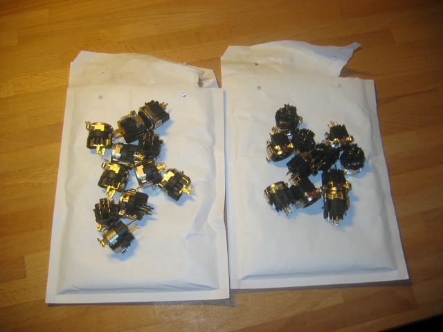
- 22 Neutrik XLR connectors for input and output
- 11 Card edge connectors

you will need:
- PSU connector (your choice)
- jumpers / headers if you want to have modular stereo link / grounding options
- 8 pin Molex (3,96mm pitch) connector if you don't want to wire the PSU connector directly to the PCB
- solder
 
I will start this

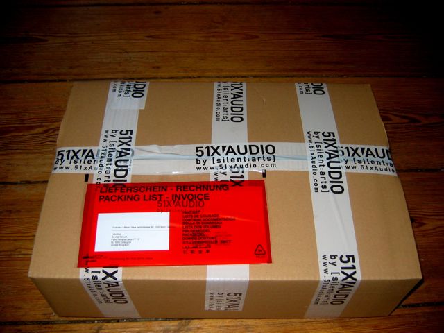
the package you will receive might look like this (depending who sends it):
IMG_5873.jpg


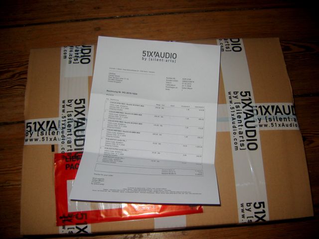
you will find your invoice (called RECHNUNG) in the red envelope:
IMG_5874.jpg


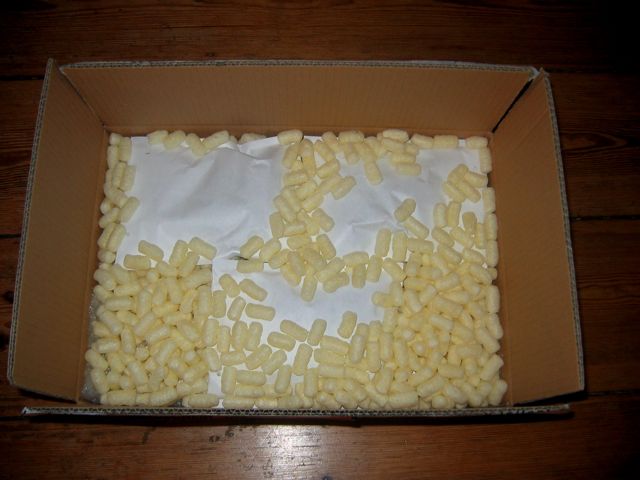
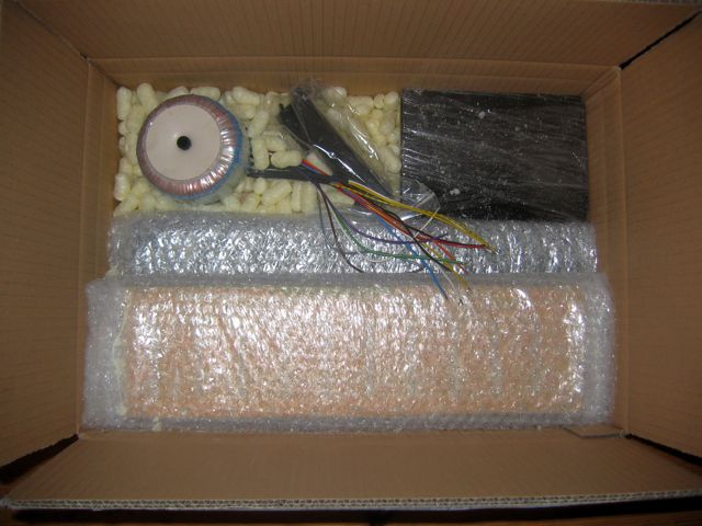
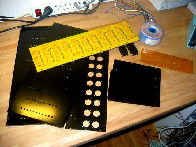
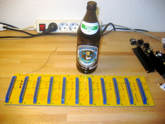
once you opened the package, it hopefully looks like this:
IMG_5875.jpg


note, those yellow things are biological material, but don't eat it
 
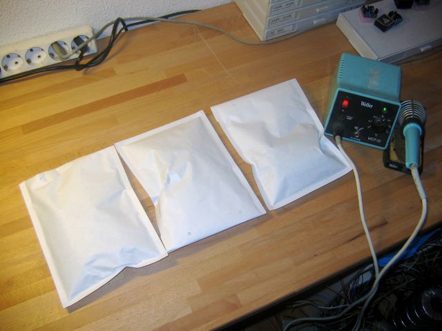
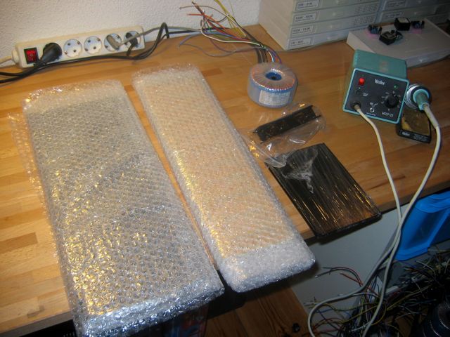
we will start unpacking the first layer, and the soldering iron ;)
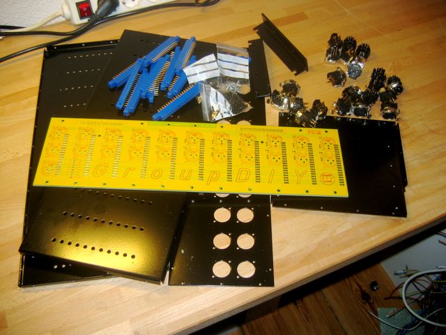
IMG_5876.jpg


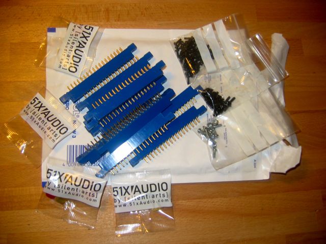
now, one bag will contain:
IMG_5878.jpg

great, 11 of those nice card edge connectors from Jeff,
3 bags with screws, and some Gummibärchen for your children.
please don't mistake the bags of screws and sweets ;D
 
Sorry, this will be a repeat post but  just an advice on the assembly.

There are two types of screws used for the assembly. For mounting the Neutric connectors and the back panel M2.5 is used. For the side panels and the rack ears #4-40 UNC. The module mountings are also #4-40 UNC. Few spare screws are included within the package.

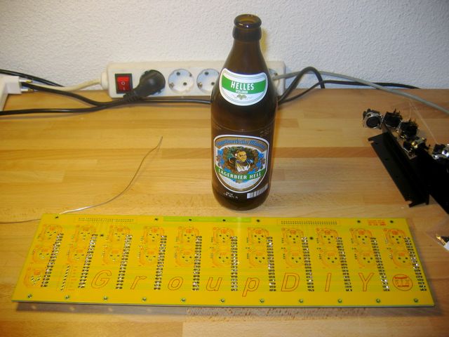
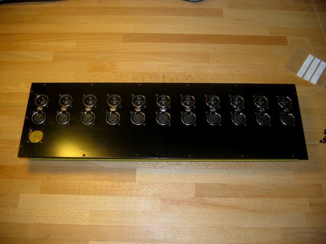
For assembling the PCB, first 18 pin edge connector should be soldered, then the Neutriks. When you are soldering the Neutriks, first solder only one pin not three of them. Once all of them are soldered onto the board through one pin keep the board on your desk flat, edge connectors faced down. Lay over the back panel and screw all the Neutriks using M2.5, then turn back the board  and solder the rest of the pins.

This is very important. If you first solder all the Neutriks and then try to mount the back panel, there is the possibility of a slight misalingment due to number of connectors involved, resulting in distorting the PCB.  And distortion on your PCB may ultimately have an effect on how your rack sounds ::)  ;D ;D ;D


gdiy_511x_assembly_1.jpg

gdiy_511x_assembly_2.jpg

gdiy_511x_assembly_3.jpg

gdiy_511x_assembly_4.jpg

gdiy_511x_assembly_5.jpg

gdiy_511x_assembly_6.jpg
 
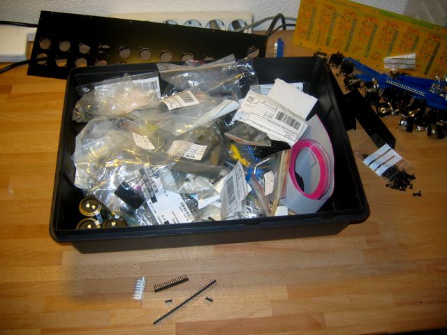
after removing the first layer we should see something like this:
IMG_5880.jpg

note, the removed package material should be used for your next parcel you ship out.

IMG_5881.jpg
 
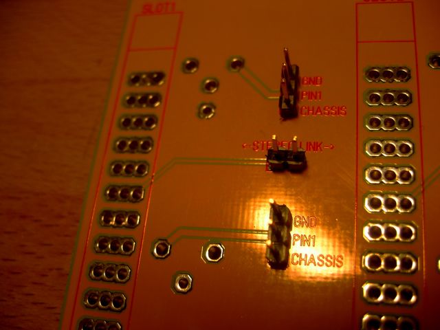
one channel jumpers
IMG_5887.jpg


note: you don't necessarily have to do this.
if you don't have / or plan stereo linkable dynamics, leave that jumper out.
if you use the provided Neutrik female connector, you can hard wire PIN1 to chassis.
you can hardwire the output too, I would recommend to chassis.

or, which is the best, use those pin headers and jumpers!
 
396 solder points / one beer / 3 phone calls / shopping for more beer later ;D:

IMG_5888.jpg


IMG_5889.jpg


those card edge connectors from Jeff solder just better than the originals Edacs I used before :D

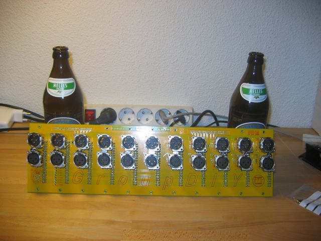
now we will do what Sahib suggests, soldering one pin (preferable pin 2) of the XLRs
 
stuffing the XLRs without soldering works fine.
screwed them. will solder now.
IMG_5891.jpg


note: you should have soldered either the Molex PSU connector, or the PSU connector of your choice already!
 
even augustiner is bavarian it is good :D

Holger, I see this in the tracking:
Die Sendung wurde sortiert und befindet sich auf dem Weg in die zuständige Hermes Niederlassung

Lukas, what is the deadline for friday ???

btw, soldered ...

now up to the metal work ;D
 
ok, I'm dump with metal work ...
I see two identical top and bottom panels.
different holes each side.
I think the 11 holes are for the front, the six holes to the back.
two identical side panels too.
Me thinking the side with the 3 holes is the back, will try it out.
 
Back
Top