The official GroupDIY 511 Help & Support Thread

GroupDIY Audio Forum

Help Support GroupDIY Audio Forum:

This site may earn a commission from merchant affiliate links, including eBay, Amazon, and others.
Nothing to do with this but Augustiner is a killer beer ;D, i still have some here from last years Octoberfest, i enjoy them as much as i can, i always chill in the Augustiner house when going to Munich Octoberfest!!!
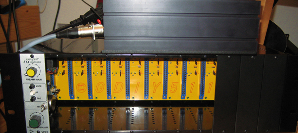
PS: the case looks great :)
 
Bashert said:
1. What is the specification for the pin headers I should buy for the jumpers?
2,54mmpitch

Bashert said:
2. What are the two separate rows of two holes at the top of the board for?
3. What socket do I need to buy to solder into those?
those are for other, maybe future options like SubD25 connectors instead of the XLRs etc
don't buy anything for it, don't solder anything there yet.
 
ACHTUNG ACHTUNG, ATTENTION PLEASE

please STOP building the metalwork if you already received the kit from me.

you all know I'm very bad with metalwork, so I build my unit wrong :-(
I thought it is me why the screws on the side went in a bit hard,
but I used the wrong screws ...

fact is, because of this I did send you the wrong amount of screws!
DON'T use the M2.5 for the side panels, they need to be #4-40.

since those are hard to get in Europe I will pack them now and go to the post office.
sorry for this,
Volker aka "best metalworker ever"
 
To make it easy, for all work done on the back panel use the M2.5 pan head screws.

M2.5 get used no where else.

So, for the Neutriks and the around the perimeter of the back panel, you will need to use a total of 66 M2.5 pan head screws.

Cheers, Jeff
 
Can I just re-iterate how crucially important it is to make sure the jumpers used for grounding/stereo-linking are long enough on the solder side! The standard ones are NOT - unless they are modified by slightly pulling the pin through the plastic.

I would highly recommend to solder a few and try if they actually stick, as mine are now falling out one by one, leaving me with a very difficult to de-solder pin hole (due to the thickness of the PCB).

The EDACs are easier to solder, but I learnt (the hard way....) to make sure the connector is plan with the PCB after the first few solder-spots. then continue with the remaining ones (of which there are quite a few...)

hope I can help other people repeating my beginner mistakes....
 
And the winner is: Holger  ;)
At least I'm the first one who is able to post photos of a technically finished unit. Still waiting for my front panels.
This was the first time my VP2x came in contact with electricity; works wonderful...
511front.jpg

511rear.jpg

511psu.jpg

 
Hi Holger,

Congrats, yes you are the winner !!

What psu connectors did you use ? The 9 Pin connectors from RS found by Sahib ?

Wolfgang
 
I just finished putting in my jumper headers and have 2 questions:

What would be a good default for grounding?

Why is channel 4 not connected to stereo link on either side? Not a big deal as I don't have any stereo modules but just curious, there are no traces to it.

Thanks guys, can't wait to start using this thing.
 
benlindell said:
I just finished putting in my jumper headers and have 2 questions:

What would be a good default for grounding?
personally I do ground all pin1 to chassis.
brio had an issue with this with an original API 512, not providing phantom power than.
which I can't understand, but he solved it with jumpers from pin1 to ground at the input.

benlindell said:
Why is channel 4 not connected to stereo link on either side? Not a big deal as I don't have any stereo modules but just curious, there are no traces to it.
:mad: :mad: :mad: :mad: ::) ::) ::)
it is not needed since you wont ever want to link module 4 to 5 ??? ??? ???

Holger said:
Nice bug finding  ;)
sadly true :'(
ok, next one PCB batch is rev03, tooling costs again - fuck.
sorry for this bug, and nice someone found it :)
 
So for wiring the power connector on the rack. The holes on the PCB where the connector goes aren't connected to the +/-24 Power rail, I'm using wires anyways, is that what everyone else is doing instead of using the PCB mount 6pin connector?
 
benlindell said:
So for wiring the power connector on the rack. The holes on the PCB where the connector goes aren't connected to the +/-24 Power rail, I'm using wires anyways, is that what everyone else is doing instead of using the PCB mount 6pin connector?
the holes for the PSU connector, and the 5pin XLR printed on the back silkscreen, is +/-16V only.
using this one is original API PSU compatible, but you will have a loss of the benefits of 51X.

use a wired connector, there is that molex connector on the back of slot 10.

nice work so far :)
 
Sorry if this has been answered... but do we NEED the 9 pins to get 16v and 24v? or will 7 just do (much easier to find cable for too!)

I did see that 5 pin (wooo dmx!) will get you just 16v, but surely if you had a common ground 7 pin would do just fine yeah?
 
Back
Top