Transformerless Vari Mu Compressor build thread

GroupDIY Audio Forum

Help Support GroupDIY Audio Forum:

This site may earn a commission from merchant affiliate links, including eBay, Amazon, and others.
Am I suppose to set the input gain at a certain position? how much voltage should the 50hz be sent at?
Whatever it takes to get the 8db leds to light up.

I have also tried with the file but I am not sure if I need to adjust both trims for less thump
Yes...well you may not "need" to but you're looking for lowest thump.

Also channel 1 is louder than channel 2
The thump? If so, not out of the ordinary as the tubes will usually not be identical. If you're talking about calibrated levels, that's a different adjustment.

With fully clockwise trim I have a difference in voltage between both boards 3.89v and 4.15v before adjusting. Should they be same voltages with trim fully clockwise?
Mine weren't, although they were a little closer. I'd say it doesn't matter but never asked.

Also, if someone can explain to me what the link does? Which board becomes the controlling board, ?
I asked about this a couple of times as well. Here was one of the responses from Heikki

"Link sums the control voltages together by paralleling the ratio pots. Which means the best way to adjust the ratio when link is on is to turn one ratio pot to max and use the other ratio pot to adjust ratio. To make the channels act as close to identical as possible attack, release and threshold should be on same position on both channels. This way of implementing the stereo link isn’t perfect but if absolute perfection and accuracy is needed then anything with tubes should be avoided. In my opinion stereo link is useless feature anyway and I only use it when checking tube balance.

Now that I actually think about it. I think I came up a better way of making the stereo link. The point where D2 and D3 anodes are connected together, wire the link switch to connect that point together on both boards. Try it first with a jumper cable and see if it works. That way the attack, release, threshold and ratio should be adjusted to same position to get perfect stereo link and there would be no confusion with the parallel ratio pots"

"Before removing the original way of linking try if the other method is better. If you don’t use the link you might ass well leave it like it is. There shouldn’t be large difference which way the link is implemented. "


If I noodle with some audio file I need to raise the input fairly loud to hear and see some compression and thus increasing the overall volume, which makes it a little hard to compare when bypassing as the loudness is affecting the judgement
Yeah. Some type of gain stage structure in the chain is useful.
 
Last edited:
I am having trouble understanding the testing, I have the right voltages around except for 182v which is 180 and 12.6v on F which is 12.4

The voltages are more than close enough. I think Scott answered everything else.

About the signal levels. The compressor is designed to work around pro audio nominal level of +4 dBu.
 
Last edited:
Ok thanks guys, so I'm not too far out then, Still one channel is louder than the other one when compression audio.

How much should they light up the 8db leds? barely or full on?

Is there a way to adjust balance between the channels?
I can clearly see that one channel is also lighting more LEDs than the other one

Now I clearly realise that if I set the voltages for the side chain boards to be same on both boards then the less behave exactly the same, so should I do that?
Channel one has 3.89V and channel 2 4.15v Should I set both at 4.25v?


Manu
 
Last edited:
The link won’t give you perfectly same amount of compression but it should be fairly close if attack, release and threshold are exactly same on both channels. When not using stereo link even if attack, release, threshold and ratio are adjusted exactly same, most likely both channels won’t behave exactly same. Unless you of course have perfectly matched tubes between the channels

It doesn’t matter how much the 8dB led is on when adjusting the balance. We are working with tubes, nothing is too precise.

Small adjustments to the idle bias voltage are good for getting exactly same gain on both channels when NOT compressing. But if you want exactly same behavior on both channels you would need identical tubes on both channels. The gain reduction meter leds light up at some amount of control voltage and the actual amount of compression will depend on the tubes. I encourage anyone building this to buy few extra tubes to try if you need to get the channels to behave the same
 
Alright i see, I am trying to get this into my bus chain and when i set it up with exact same ratios (in link position) i get a clear difference in balance between left and right. Few dbs... that's what i was trying to get. I understand the tube matching but was wondering if there was anything i could do to try to get the volume match closer. I can't tell really what amount of compression is applied but it's more of a volume issue.

I can try with more tubes sure, could maybe get it closer...

When doing the setup, i've gotten the voltage on output of other channel at 0v. What is the -40dbu refering to? And what is that doing in practice? I'm just trying to also understand the concept in that trim.

Thanks again, was a joy to build
 
Also one thing that i find very odd compared to other compression i own is that as i increase the gain and compression starts kicking it, the volume gets louder as well.. with other compressors i own, 1176, ssl, neve, la2a The make up gain is there is help the loss of volume due to compression.
How is this design different?
Thanks for the clarification

Manu
 
https://en.wikipedia.org/wiki/Decibel#Voltage
-40 dBu would be 0.008V RMS and would show as 0.008V or 8mV if you are using AC voltage meter to measure the signal. If soundcard/audiointerface is used to measure the signal then you should know what -40 dBu would be in dBFS in your system.


https://en.wikipedia.org/wiki/Dynamic_range_compression#Ratio
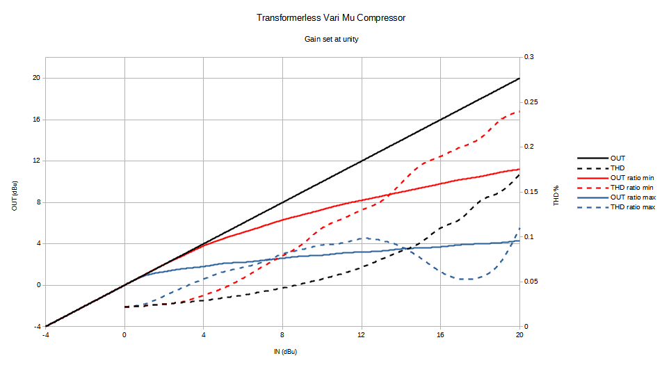
The volume/gain pot is before the variable gain stage and since the ratio is less than infinite the output level will always rise when input level rises. Since there is no output volume control in some cases there might be need to pad the output. Perhaps if used with gear with -10 dBV nominal level like old tape recorders for home recording use. But interfacing different types of gear should be in the basic skill set of an audio man.

6sk7compchart.png
 
Is there a way to adjust balance between the channels

Could measure to determine where difference(s) in balance btw channels originate:

- input GAIN pots
- tubes
- tolerances of THR and RAT pots
- some unnoticed resistor mismatch

[Aside]
E.g. PRR's 'vari-mu' used/uses threshold pot not really for setting THR but for balancing tube mismatch (there before rectifier though). So here stereo link as drawn in SC schematic makes sense, I think
[/Aside]
 
Here's how to determine where the difference is.

On both channels adjust attack and release to fast position, ratio to max, threshold to max and gain pots to max. Feed -10 dBu 1kHz sine wave to both inputs. Monitor the outputs on both channels. Lets say channel 1 has +7 dBu output and channel 2 has +6.9 dBu output. To get the gain on both channels to same adjust RV1 on channel 1 sidechain board until the output is +6.9 dBu. If there is more than 0.5 dB difference in the channels you might want to try different tubes and not even bother with adjusting the trimer.

Next turn threshold on both channels to min (do NOT have link on). Now monitor the output on both channels and check that the output level on both channels is within 0.5 dB. If there is more than 0.5 dB difference on the channels you might want to try different tubes. Also check that the same amount of LEDs are lit on both of the gain reduction meters.

If these tests give satisfactory results then the channel differences are most likely caused by pot tolerances. On the extreme ends the pot tolerances won't make large difference but somewhere in between it's a different story.
 
Last edited:
Great to see a Vari-mu project out there, there tends to be a lot of Opto compressor projects but not many Vari-Mu’s with attack and release controls.
I’d be up for a set of PCBs when they’re back in stock. In hope to change the pots for rotary switches and hopefully make a nice mastering compressor 👍
 
Sounds great thank you all.
I will check everything as noted. I have Rotary switches instead of pots for gain, which is really nice :) I matched the resistors.

I'll get back to this as soon as i have results :)

Manu
 
As for pots, could try to match pairs as best possible from pins 1 to 3, and in second step to wiper at eyeballed mid position. Should the wiper at mid position be way off, it's either eyeballed wrong or the pot is indeed a foul egg.
 
I'm just gonna ask again to be sure i got the reply to this, cause somehow i can't find it.
When adjusting the voltage on the sidechain boards. Having the trim pot fully clockwise i have different voltages :
Channel one has 3.89V and channel 2 4.15v Should I set both at 4.25v? or should i set like recommended channel 1 at 4V and channel 2 at 4.25v.
That clearly has an effect on how my LEDs are lit

Manu
 
Read Heikki's reply #30 again ;)

Also I'd make sure that all fixed onboard resistors in both SCs are matched between boards. Luxury of DIY.

Monitored outputs read same dBu but LED still mismatched ? Could swap tubes left right. Your lit LED mismatch follows or stays the same ?
 
Read Heikki's reply #30 again ;)

Also I'd make sure that all fixed onboard resistors in both SCs are matched between boards. Luxury of DIY.

Monitored outputs read same dBu but LED still mismatched ? Could swap tubes left right. Your lit LED mismatch follows or stays the same ?
Haaa stupid me, i thought this was still to get the balance between channels... Thanks and sorry for asking twice...
I will try that and see if it fixes anything, then will try swapping tubes :)
 
I'm just gonna ask again to be sure i got the reply to this, cause somehow i can't find it.
When adjusting the voltage on the sidechain boards. Having the trim pot fully clockwise i have different voltages :
Channel one has 3.89V and channel 2 4.15v Should I set both at 4.25v? or should i set like recommended channel 1 at 4V and channel 2 at 4.25v.
That clearly has an effect on how my LEDs are lit

Manu

If the voltages are 3.89 and 4.15 then follow the instructions here and adjust the 3.89V to 4.00V and 4.15V to 4.25V. After that do the measurements and adjustments from post #30.
 
After all the tests and measurements are done and everything is reasonably matched between channels and you have the older version of the LED boards. There might be need to change R6 on the LED boards if the 1dB led glows brightly when not compressing. In that case R6 should be changed to 12k. The latest revision of the LED boards has a trimmer for this.
 
Here's how to determine where the difference is.

On both channels adjust attack and release to fast position, ratio to max, threshold to max and gain pots to max. Feed -10 dBu 1kHz sine wave to both inputs. Monitor the outputs on both channels. Lets say channel 1 has +9 dBu output and channel 2 has +8.9 dBu output. To get the gain on both channels to same adjust RV1 on channel 1 sidechain board until the output is +8.9 dBu. If there is more than 0.5 dB difference in the channels you might want to try different tubes and not even bother with adjusting the trimer.

Next turn threshold on both channels to min (do NOT have link on). Now monitor the output on both channels and check that the output level on both channels is let's within 0.5 dB. If there is more than 0.5 dB difference on the channels you might want to try different tubes. Also check that the same amount of LEDs are lit on both of the gain reduction meters.

If these tests give satisfactory results then the channel differences are most likely caused by pot tolerances. On the extreme ends the pot tolerances won't make large difference but somewhere in between it's a different story.
I tried that and I have +6.55dbu and +7.05 dbu on the outputs when feeding -10Dbu 1khz sine

So I guess I need to work with tubes?

Otherwise the compressor sounds amazing... just tried it on a mix... WOW, I can manage without using link but I have to set the thresholds at very different points to match the left/right balance which is ok but a little difficult since working with stereo mixing I am not sure of the respective volumes etc..

If the tube swap is my only option to find a better output dbu match then I have to go down that road. I am using NOS 6ss7 and the local dealer still has 20 or so available...
Any way to match them without doing it inside the Vari mu? Id love to close the lid on this thing when I can have an acceptable left right balance. The volume increase isn't a big deal, I can always adjust obviously

Thanks again for the help
Fantastic project ! will have to make another one :)
 
Last edited:
I tried that and I have +6.55dbu and +7.05 dbu on the outputs when feeding -10Dbu 1khz sine

So I guess I need to work with tubes?
Am I right if assume that channel which originally measured 3.89V gives the +7dBu output?

You can trim or try different tubes. I would probably just adjust the trimmer.
 
Am I right if assume that channel which originally measured 3.89V gives the +7dBu output?

You can trim or try different tubes. I would probably just adjust the trimmer.
That's right ! Which trimmer?
on SC board? An only trim the board that gives higher output?
 
Back
Top