Tube Distressor

GroupDIY Audio Forum

Help Support GroupDIY Audio Forum:

This site may earn a commission from merchant affiliate links, including eBay, Amazon, and others.

lernith

Well-known member
Joined
Aug 25, 2005
Messages
59
Location
Eugene, OR
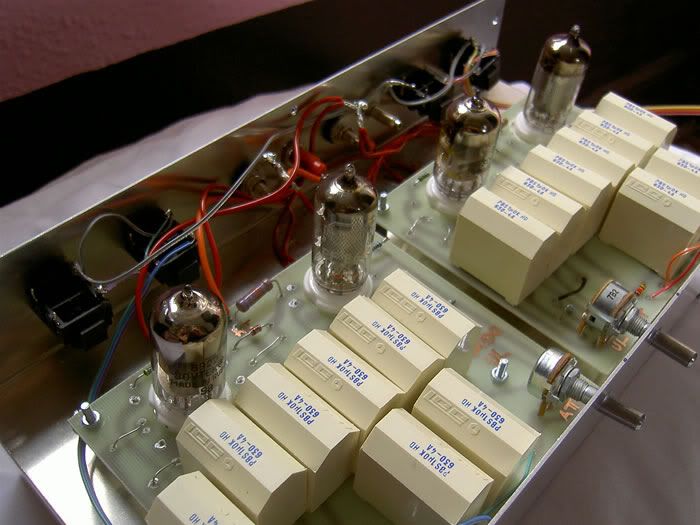
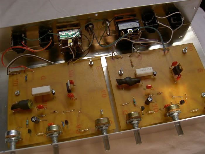
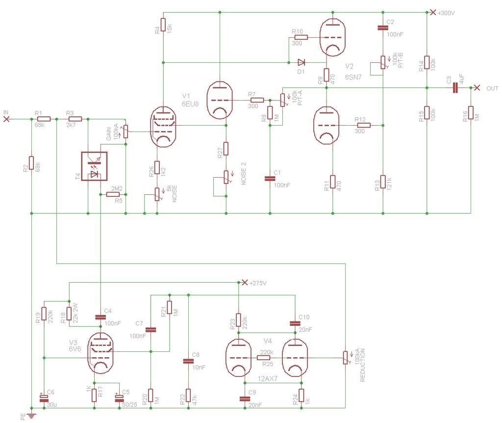
Here's something I wanted to get some opinions/perspective on.  The goal is to make a tube compressor/distressor.  I plan to use it unbalanced.  The compressor (that is to say, the sidechain and reduction bits) are straight from an LA-2A (or rather, a version of the LA-2A that CJ streamlined); the make-up amp / distressor is the Ultra-linear Aikido amp (introduced here: http://www.tubecad.com/2006/06/blog0069.htm ).  This amp is supposed to be able to blend between pentode and triode operation, which I hope will lend different types of distortion.
The bias for V1 is fiddled with and that will cause nonlinearity in a hopefully pleasing manner, à la the Thermionic Culture's “Culture Vulture”.   I will probably experiment with a pot on the triode section of V1 as well.  The pots will have a range resistor that will make the valve linear when the pot is fully CCW.
I've never tried this sort of thing before; the design might be laughable. 
But, um, no laughing plz.
Let me know what you think of the application and the math.  The 5k “Noise” pot was somewhat arbitrary.  Probably too high to have a useful range.  I really need to practice with those linearity charts.  No giggling!
My brother got me a huge box of tubes off craigslist for Christmas, so hopefully I'll get that practice.  That was a fun carry-on at the Denver Airport.  It'll be a little while before I get the rest of the parts, but I hope to have one running soon, and will post sound files....
Thanks in advance for any comments!

tubedistressor-1.jpg
 
I was doing the wrong calculation for the cathode follower.  R6 I can't figure out (do you use absolute values?  I keep getting negative 122 Ohms  ::) ).  Is formula 2b on this page ( http://www.euronet.nl/~mgw/background/tubes/uk_tubesinfo_1.html ) the right one for this?  Where Ra = 5kOhms, u = 40, V= 300?  Also I had the wrong value for R8 for some reason (300 ohms instead of 1M).  These have been changed on the first post. I saw a few hints that making R6 (the cathode resister for the cathode follower) smaller will load down the previous stage, so I think I'll try setting it up to drop in value.  Although-- the cathode follower will be out of the circuit when the make-up amp is fully in pentode mode, right?  That might make for frustrating tweaking.  Probably worth trying anyhow.  Poor little pentode.  Never did nobody no harm.
I'll keep plugging at this....

 
I have found this circuit. It seems to do something of similar of the culture vulture.
May be interesting to know if someone has realized it ...http://<a target='_blank' title='ImageShack - Image And Video Hosting' href='http://img185.imageshack.us/my.php?image=tubalizeriz0.jpg'><img src='http://img185.imageshack.us/img185/9011/tubalizeriz0.jpg' border='0'/></a>
<a href="http://g.imageshack.us/img185/tubalizeriz0.jpg/1/"><img src="http://img185.imageshack.us/img185/tubalizeriz0.jpg/1/w712.png" border="0"></a>
 
<a target='_blank' title='ImageShack - Image And Video Hosting' href='http://img185.imageshack.us/my.php?image=tubalizeriz0.jpg'><img src='http://img185.imageshack.us/img185/9011/tubalizeriz0.jpg' border='0'/></a>
<a href="http://g.imageshack.us/img185/tubalizeriz0.jpg/1/"><img src="http://img185.imageshack.us/img185/tubalizeriz0.jpg/1/w712.png" border="0"></a>
 
I am sorry, but I have no experience to place links.. :eek:
This is the link for the schematic:
http://img185.imageshack.us/img185/9011/tubalizeriz0.jpg
 
Fablab said:
I am sorry, but I have no experience to place links.. :eek:
This is the link for the schematic:
http://img185.imageshack.us/img185/9011/tubalizeriz0.jpg
This circuit is typical of the "starved-plate design", i.e. a basic tube circuit with low plate voltage making the tube operate in a non-linear zone. The "interesting" (?) point is that the tube is connected as a cathode follower, thus somewhat negating the intended effect (cath follower is inherently self-cancelling distortion).
I haven't tried this particular implementation, but I know that ALL the ones I have tried have no likeable character at best, or sound like a caricature at worst.
Anyway, it's an easy project, and making mistakes is part of education...
 
> a target='_blank' title='ImageShack - Image And Video Hosting' href='http...
> I am sorry, but I have no experience to place links.. 

You tried to do it with "proper HTML", the fancy code that ImageShack pages gives your.

If raw HTML were allowed in forum posts, bad people could post scripts and other evil code.

Most forum boards use a special syntax which supports only a few HTML features.

TinyPic.com gives you "for Forums" code which will work here.

I can't make the code that ImageShack gives you work here.

Since you found the "naked" URL for the image, this code will (usually) work:

Code:
[IMG]http://img185.imageshack.us/img185/9011/tubalizeriz0.jpg[/IMG]

tubalizeriz0.jpg
 
> cath follower is inherently self-cancelling distortion

Only when load is much higher than cathode impedance.

If you have a happy plate-loaded amp, and move the say 100K plate load into the cathode, AND keep the bias-point and OUTput signal the same, gain goes to unity and liniarity improves roughly as much as the gain which you lost.

But when grid and cathode resistors both go to common, the cathode resistor is very nearly equal to the cathode resistance 1/Gm, the cathode is heavily loaded, distortion is high and begins at output levels much lower than the plate-loaded version.

> This circuit is typical of the "starved-plate design"... "interesting" (?) point is...

Right. The Mu is much more than 1, so at any useful operating point the supply-bias will be approximately equal to supply. Say Vp-k will be 10V. Tube Mu is say 20. The grid-cathode voltage for partial-current wants to be 10V/20= 0.5V. The grid-cathode voltage for maximum-current is of course zero; but in this plan that can only happen if cathode resistOR is very-very small. 

The maximum peak signal output is not going to be much over 0.5V. So for any "hi-fi line level", this is a "LARGE-signal" amplifier.

Cathode resistor is variable 2K to 50K.

Tube current is roughly 0.5V/2K to 0.5V/50K or 0.25mA to 0.01mA.

Gm at these low voltage and currents will be 500uMho to 100uMho, so rk will be 2K to 10K.

At 2K at "POT", the cathode is heavily loaded, not linear, and in-trouble for 0.5V peak signals.

For 50K at pot (and NO external load), the load is not toooo heavy (50K against 20K), nonlinearity is not too awful, though it will still clip "nominal" signals.

> it's an easy project

Exactly why he should build it. As you say, experience is the best teacher. 
 
It is nice to think that if this bundle doesn't work than through the miracle of PTP I'll just rearrange things and cock up in a new and unique way  :D
 
You can use similar trick with a transistor (emitter-follower).

One drawback of using a potentiometer to (sort-of) re-bias is scratches and noise that can (o.k. will) occur when adjusting. One way to counter that is to use a current mirror (two for stereo) as a load. This way, you can use a single potentiometer to adjust two channels at the same time.

Transistors in the current mirrors must be matched (resistors as well). Additionally, use a capacitor to smooth out the potentiometer noise.
 
making it somewhat quicker...

I built a 4 channel compressor of those ultra-linear aikidos (ef86/e88cc as first schematic) and stuck them behind a hacked FF/FB simple led opto schematic with fet side-chain from Scott Dorsey.Works wonderfully.

pict2105.jpg


(last transistor is 2n3904 not pnp 2n3906 as drawn)

Heaters all AC (yep!) and all unbalanced signal.
here's the tube section of 2 channels in the modular rack build...I had a huge box of 1uF poly caps to whittle down at the time.
This is my preferred method for tube circuits these days,hand drawn traces lined in with solder for reliability,on boards to hold components but the tube socket is independent in the hole.LT doesn't touch the board.So it's a mixture of hard wiring and board:easier than spending time mounting components to tag board.


tubesection.jpg


Instigated controls: Sidechain Gain,Attack,Release and Make-up gain , UL control.
250V,6.3V,15V with onboard 7812s for each sidechain.
Sidechain 2n3819s and 2n3904s.Yellow leds/ldrs hidden in heatshrink.
Very quick project with my big Fluke HT supply.

here's the sidechain for two channels,all boards self drawn inkpen then etched

optosection.jpg


The Broskie circuit on its own teaches you beautifully about pentode vs.triode harmonics.Highly recommended.

Only caveat in my application is some hiss if I don't set the preceding gain structure correctly.

Robert

 
Nice build! Great looking work. I still do all my tube stuff p2p.

One rectifier diode in sidechain. Half-wave.... huh. You find it compresses effectively, even on lopsided waveforms?

I do think the combination of smooth-but-slow opto with quick to distort (nicely) tube gain stages is often a winner.

 
Nice build! Great looking work. I still do all my tube stuff p2p.

Thanks.I've got a hi-fi preamp coming up which I'll do strictly rat's nest p2p -not even turret boards- but this was four channels and a battle between everything one might achieve and what actually finds itself made.

That's why I detailed it here.It's quick to do.

I found I get a lot of projects done by etching my own crude 60s tape style circuit boards, I have a childlike fascination with etching-kettle,washing-up bowl,spotlight,dirty brown chemical.And once done I feel obligated to fill the board before the tracks oxidise!

It also works well without strapping oneself into ambitions of all-tube sidechain and balanced in and out which can destroy a project far quicker than a cold solder joint.

Robert
 
I get some mail on my hack adaptions of the hampton compressor sidechain.
Why he used an opamp to decouple the attack/release from the led transistor chain I don't know, perhaps he wanted to teach about dual supplies at the same time.
Anyrate the boot-strapped source follower as hacked in is cribbed directly from
martin hartley jones "A practical introduction to electronic circuits" which in the 1985 edition is currently less than $2 on amazon which is cheaper than the 2n3819
Values are 1k for the resistor directly below the fet which sets the bias,3k3 for the resistor to earth below the 1k which is our load resistor and 2m2 for the bootstrapped resistor between the gate/input and junction of the 1k and 3k3.

The resistor below the 2n3904 sets the maximum current through the led.You can use any led calculator on the net.
All it does is subtract 2-3V from the supply then apply ohms law to determine the resistance for probably 20mA of current.
So 9/0.02 etc.

I must stress that the killer part of this adaption is the use of the Aikido ultra-linear as the make-up where you can dial in triode or pentode distortion characteristics.That really sets it apart.
Note the design needs gain,feed it a weedy signal and it will output plenty of hum and noise.
Feed it some fire and it will crush yer socks off.


Robert
 

Latest posts

Back
Top