rmaier
Well-known member
How does this impact the question of metering? Are we back to running a VU meter and trimmer parallel to the 2K series resistor?
Ralph
Ralph


rmaier said:How does this impact the question of metering? Are we back to running a VU meter and trimmer parallel to the 2K series resistor?
Ralph
rmaier said:Thanks, Ian. Parts will be trickling in over the next little while, so I'll start building very soon. I'll leave enough space on my perf board to accommodate a few options for linking.
Ralph.
ruffrecords said:I think he means this:

rmaier said:Good idea. I'll give it a go.
ruffrecords said:I think we can retain the 1K8 in series with the 200 ohms and the meter connected across the 200 ohms. All that has changed is the means by which the two channels are linked. We now switch LEDs rathe than coupling the 2 x 200 ohms together.
If we do it like this you can always try out either or both coupling methods.
Cheers
Ian
rmaier said:I've stuffed my TLA boards and placed the vactrols and VU circuits on perf board. I don't have any 200r resistors handy... can I get away with 220r or should I wait until I can make another trip to the electronics shop? I spend too much money there, and it's a long drive across town for two resistors!
Ralph
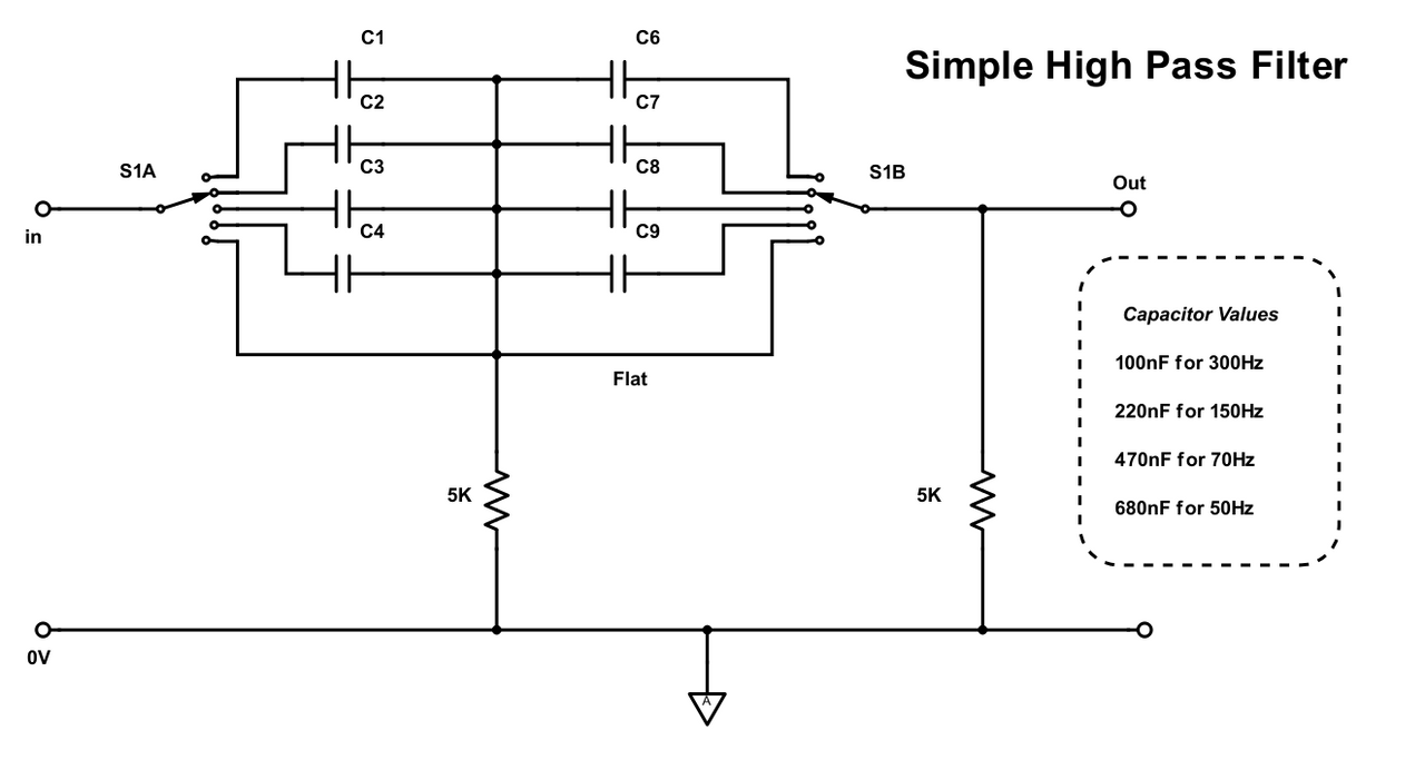
rmaier said:This looks worth pursuing. I have some 2 pole 7 position open frame switches that I could try. Hmmm...
How does it work?
Thanks!
Ralph


![Soldering Iron Kit, 120W LED Digital Advanced Solder Iron Soldering Gun kit, 110V Welding Tools, Smart Temperature Control [356℉-932℉], Extra 5pcs Tips, Auto Sleep, Temp Calibration, Orange](https://m.media-amazon.com/images/I/51sFKu9SdeL._SL500_.jpg)


