rmaier
Well-known member
Thanks, Ian. Glad I asked!
Ralph
Ralph


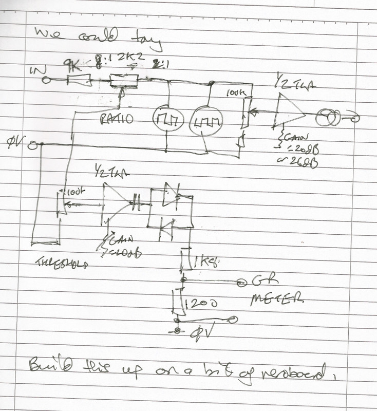
pvision said:Ian, just make the transistor sidechain and mount it on a valve base. No-one need ever know
Nick Froome
rmaier said:Hi Ian,
As it happens, I've been working again (after a break - life seems to interfere far too much with DIY) on putting a pair of these into a single box, so I'm reading your posts with great interest. Are you thinking something along the lines of a stepped ratio switch?
I'm still early on in my build, so it might be possible to try to integrate some of your recent ideas.
Ralph
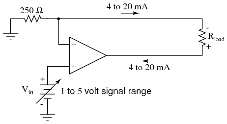
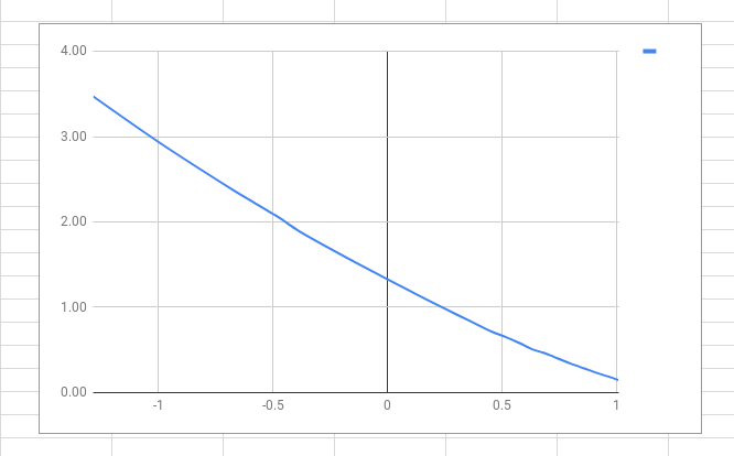
ruffrecords said:One of the issues with asemiconductorop amp side chain is you cannot use the simple technique of driving up to 20V rms through a 1K resistor to drive the LEDs because you would ned +-30V power rails. But you can do things with op amps you cannot easily do with tubes. For example a voltage to current convertor is easy to make:
This example is aimed at instrumentation but you can just replace Rload with a pair of back to back LEDs in Vactrols for a compressor. The 250R resistor sets the gain at 4mA per volt. In some ways this is ideal for driving LEDs because the op amp takes out their forward voltage drop. This allows us to set the threshold in some other way more under out control, using a regular diode for example. So maybe a couple more op amps for a precision rectifier followed by the diode and a cap like any other compressor, This would give us some control over attack and decay times and possibly simplify stereo linking. Maybe a couple of NE5532s would do the job.
Cheers
Ian


![Soldering Iron Kit, 120W LED Digital Advanced Solder Iron Soldering Gun kit, 110V Welding Tools, Smart Temperature Control [356℉-932℉], Extra 5pcs Tips, Auto Sleep, Temp Calibration, Orange](https://m.media-amazon.com/images/I/51sFKu9SdeL._SL500_.jpg)