UA 610 Preamp - Transformer Substitute

GroupDIY Audio Forum

Help Support GroupDIY Audio Forum:

This site may earn a commission from merchant affiliate links, including eBay, Amazon, and others.
I’m kind of figuring this out as I go so I’ll figure out a better grounding scheme,  Could you recommend a reference? Thanks for your help here.
 
Star grounding is always a good way. The way you have it, there could be currents flowing that do not reference to the ground the rest of the tube is seeing. At the very least, star ground around that input stage. And any grid lead is at high impedance so should be as short as possible or shielded.
 
If you're going to wire point-to-point then there's a book by Morgan Jones that goes into wiring a valve circuit.  Actually, there are two books by him.  One is the theory stuff, and the other concerns actually 'Building Valve Amplifiers'".  This is written from the perspective of Hi-Fi stuff but a phono preamp is dealing with similar low voltages to a mic amp so it's useful.
There was a book by Allen Wright I had many years ago dealing with pre amps...  "Pre Amp Cookbook" maybe?  This explains how you should keep the current loop around a stage as small and tight as possible.  Always good to do this, regardless of if it's a point to point or a PCB layout. 
There's a book by Merlin Blencowe (sp?) which I haven't seen but it may also be useful. 

Anyway, you'll get there mate, keep at it 😊

 
Just coming back to the preamp build.

I appreciate the information on the reading materials.  I've browsed some of the 'Building Valve Amplifiers.'  There's a lot there.

I'm a little confused as to why I'm not able to get this preamp working without noise and hum.  I've eliminated the eq section entirely.  Bypassed the 250k potentiometer (added a 250k resistor from pin 2 to ground/ .2 cap going to pin 2)but still have an enormous amount of hum.  There is some kind of ground loop happening....?  The preamp is working, just with hum in the background...It also sounds just a touch thin.  Not a lot of low end, but that could be just that I'm testing using a 57.  Still, it seems a bit on the thin side.

I re-star grounded the preamp at two points, input valve and output valve.  Then they both separately connect to power supply cap ground. 

Maybe it's my layout?  I've built a couple of la2a's and never had this issue.  Maybe the output transformer A25's ground shouldn't be connected...?  Any ideas?  Maybe I should I use a turret board instead?

Nate
 
you could build an external power supply to run the preamp,

then you would probably have a piece of equipment with lower hum than the original.

and the same power supply could be used for future projects.

pick a chassis with a lot of room so you can add another supply for solid state equipment.

 
Damn, I'm sorry you're still having noise problems, must be frustrating.

I do think CJ's idea for an external supply is a good one. 

Although the original  LA-2a does work as wired, the fact is that it isn't a particularly good model to reference for grounding schemes.  There are places where the chassis is used as a ground return which is not a good idea.
When at Universal Audio, as experiment I built up a unit from scratch-n-dent parts lying around and used a proper grounding scheme.  When done and tested on the AP system 2, the noise was some 4dB lower.  Not necessarily a huge improvement but it does illustrate that there is a difference.
The 610 has higher gain than an LA-2a and we're also starting out with much smaller signal voltages.  Any noise picked up or induced into the front end will be amplified.
First off, assuming you are, I think it's probably a bit masochistic to use AC on the heaters of a valve mic pre these days 😉.  You can certainly minimize hum but your job is harder.
If you do have AC, have you installed a humbucker pot across the line?  Typically this would be a 250 ohm wire wound.  If you don't have a pot, you could try a couple of resistors of 125 ohm nominal with the centre point grounded.
Wiring all heater wiring before anything else and keeping it down against chassis and run off, away from signal wiring is important.
Keeping wiring from the input transformer to the first grid shielded or as a twisted pair, and keeping that loop of transformer, valve and passive parts as small as humanly possible.  Visualize or draw out the complete current loop for it so you know what's included in that loop.

Maybe your ammo box isn't giving you enough room to wire this comfortably?  It will certainly couple any and all hum from your power transformer into your signal so, again, a remote supply ameliorates that.


A thin sounding signal isn't good, and isn't how it should sound.  I don't know what you mean by grounding the output transformer though, do you mean the transformer shielding?
 
dawsonaudio said:
Thanks for the info.  I will try to address those issues.
Ian's grounding doc is a great read.
http://www.ianbell.ukfsn.org/EzTubeMixer/docs/EzTubeMixer/SimpleMixer/grounding101v2.pdf
I built a 610 clone and didn't have any probs with hum. If you're still stuck after reading that i can open it up and see what i did but sure it's just standard star ground.

edit: and this is my goto for heater troubleshooting.
Nice explanation of the humbucker pot Winston mentioned.
http://www.valvewizard.co.uk/heater.html
 
mrclunk said:
Ian's grounding doc is a great read.
http://www.ianbell.ukfsn.org/EzTubeMixer/docs/EzTubeMixer/SimpleMixer/grounding101v2.pdf
I built a 610 clone and didn't have any probs with hum. If you're still stuck after reading that i can open it up and see what i did but sure it's just standard star ground.

Cool  8) 
 
dawsonaudio said:
Just coming back to the preamp build.

I appreciate the information on the reading materials.  I've browsed some of the 'Building Valve Amplifiers.'  There's a lot there.

I'm a little confused as to why I'm not able to get this preamp working without noise and hum.  I've eliminated the eq section entirely.  Bypassed the 250k potentiometer (added a 250k resistor from pin 2 to ground/ .2 cap going to pin 2)but still have an enormous amount of hum.  There is some kind of ground loop happening....?  The preamp is working, just with hum in the background...It also sounds just a touch thin.  Not a lot of low end, but that could be just that I'm testing using a 57.  Still, it seems a bit on the thin side.

I re-star grounded the preamp at two points, input valve and output valve.  Then they both separately connect to power supply cap ground. 

Maybe it's my layout?  I've built a couple of la2a's and never had this issue.  Maybe the output transformer A25's ground shouldn't be connected...?  Any ideas?  Maybe I should I use a turret board instead?

Nate
Did this ever get sorted out?  Would be interested to know your thoughts on Cinemag vs UTC output in this circuit.  I really enjoyed the UA plug, now I'm itching to build one.
 
hey all,

I built this up, and it sounds great, with the only change being a DI i implimented between the input TX seconddary, and grid of the first triode. I am having a pretty vexing problem with noise, however. I have traced the problem to somehwere between the input transformer, and the DI input. When i send signal through the DI its dead quiet(no hum, strong signal) even at max gain, however, when its unplugged, and just being used as normal, the hum is pretty noisy.
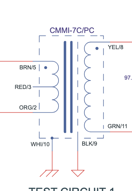
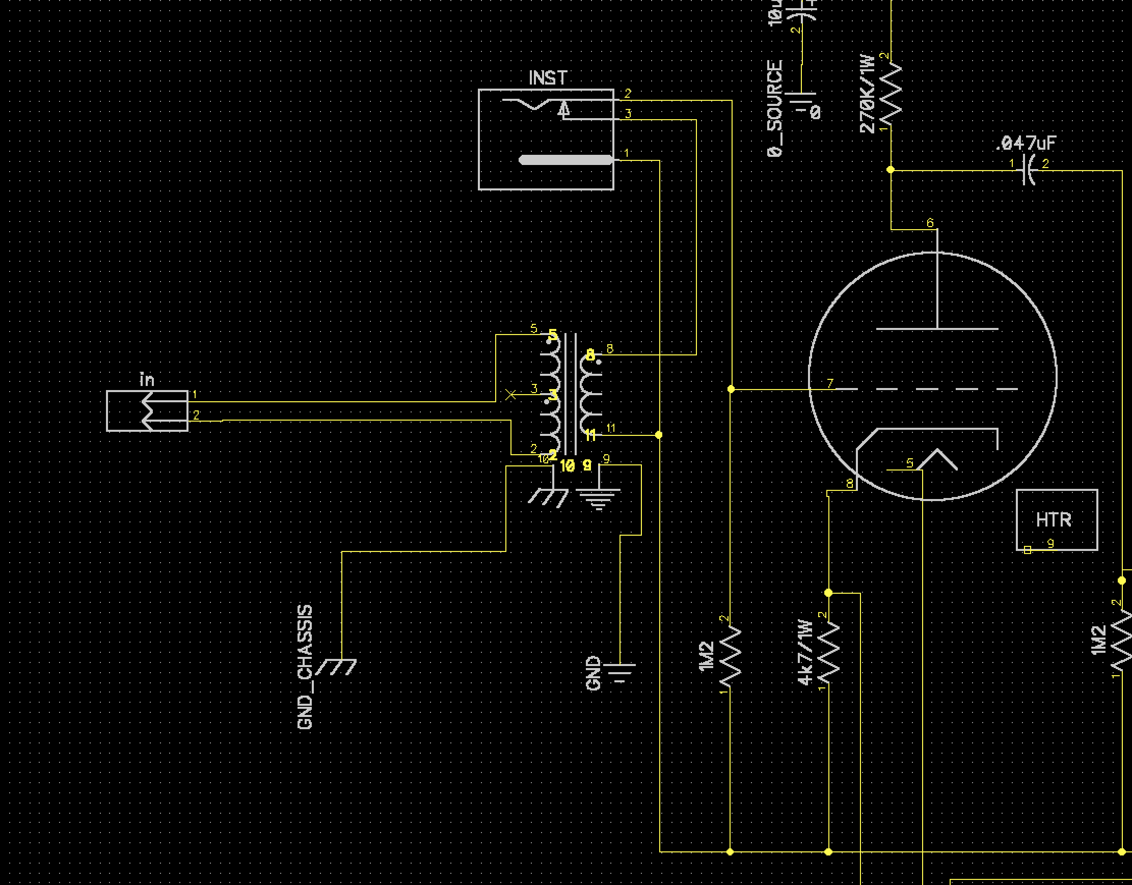
The only thing I can think of, is how i have the grounding on the input TX wired up. Its a Cinemag CMMI-7, (Pinout included below as well as a schematic showing how i have it wired)

Any thoughts?

c01gxDV.png

zHTkLOK.png
 
update for anyone curious:

it was definitely how i had it grounded. high impedence and low impedance dont mix. who'd of thought!
still a bit of 120hz hum to get rid of, but my god its night and day haha
 
Last edited:
Cool, good to know.

One thing I'd like to mention is that a friend of mine recently built one of these using my schematic and, he actually had issues with that alternate biasing scheme (never got to the bottom of it ) but found that the circuit built as in my drawing of the compete amp worked great.

He used a UTC input as in the original, and a Cinemag 7:1 gapped output.

Various samples he sent sounded 'Really nice!'
If he's reading this: Dude, I owe you emails and as soon as I get the laptop sorted and get my password for gmail recovered, I'll get back with ya.
 
Gridstopper, is the Hi-Z input jack isolated from chassis or? IOW, do/did you have a double earthing going on?

What I'd try is, making the ground point right at the first 12AX7 stage be the ground that is connected to chassis. Have no other connection from B+ ground etc to chassis/Earth. Then use an isolating 1/4" jack for the DI input.

Short cable runs from DI and mic switching etc. to that first 12AX7.

Alternatively, if using a non isolating jack, use a telescoping shield with shield connected only at the jack end.
However, I think the first way with isolating jack would be less circuitous in getting a good ground reference for both mic and Hi-Z.
 
Last edited:
I don't understand what the point of connecting the 82 pF cap between the two cathodes is, other than for convenience's sake, because on the original, it was easier than finding a nearby ground connection?

Since the triode before the gain control has a cap bypassing it's cathode resistor, the small cap is going to see ground anyhow... correct?
 
Gridstopper, is the Hi-Z input jack isolated from chassis or? IOW, do/did you have a double earthing going on?

What I'd try is, making the ground point right at the first 12AX7 stage be the ground that is connected to chassis. Have no other connection from B+ ground etc to chassis/Earth. Then use an isolating 1/4" jack for the DI input.

Short cable runs from DI and mic switching etc. to that first 12AX7.

Alternatively, if using a non isolating jack, use a telescoping shield with shield connected only at the jack end.
However, I think the first way with isolating jack would be less circuitous in getting a good ground reference for both mic and Hi-Z.

It is indeed an isolated jack! no connection to chassis there. in terms of how it was wired before i got the REALLY bad noise out, the grounds for the input transformer were to close to the ground to the grid of v1, changing that got it down to just the 120hz @ about -50dB that im currently experiencing. ive rearranged the grounds, as you suggested, and that actually fixed the gain knob which was rather noisy, however the 120hz hum is still there. id also note that ive discovered the cable that links the 250k pot to the board is fairly microphonic(seems to be the only thing that is, tapped all the tubes and other wires to confirm). doesnt seem to make a difference wether the cable is shielded or normal hookup wire, wondering if this could be the source of my troubles...

edit: it was not the microphonic cable. it was just wired kinda funny. no more microphonics, still some hum. back to the drawing board
 
Last edited:
ok! one last update(sorry to spam haha)

so i probbed through the circuit and the hum only appears at the grid of V2-b, the one that is being directly fed by the optx. getting closer...lol
 
A couple of us went to Neil Young's place to see it. The desk had originally been @ Wally Heider's.
Hi John, and all..

I have wondered, with my UA610 'solo' box, if it's possible to mid the DI/Thru aspect, to make this an isolated Thru, and if so, what's the best way to do it?

I have had issues in the past, when I use the THRU to an amp, and the Mic out (or Line out) on the back, I have ended up with ground loops on occasion.

Other boxes with 'THRU to amp' type connectors, I have used with a ground lift feature which can solve this issue, but there doesn't seem to be anything on the 610 that helps in the above scenario.

Keen to hear if there's something I can add our modify, or wheat else have people done in this situation ?

CHEERS
Evan
 
Hey Evan,
UA's 'solo' 610 box was after my time so I wasn't involved in the project.
I've never taken a close look at what's inside tbh, but I'll take a wander online now and look for inside pics.
I'm fairly sure it'll have been mostly based on the earlier 2-610 or the later M610 which was a little different in terms of power supply (H.T. was regulated and, if memory serves, I ran heaters at 12V6 DC instead of 6V3)

Anyway, It'll require a bit of a think and a ponder...
When you say you've used other devices with a 'ground lift feature' are you talking about transformer D.I boxes or?
 
ok! one last update(sorry to spam haha)

so i probbed through the circuit and the hum only appears at the grid of V2-b, the one that is being directly fed by the optx. getting closer...lol

Is it noise from the H.T. supply? That V2B is the first section that sees the main H.T after the filters, all other sections go through additional RC dropping and filtering sections so any noise will be reduced for those.

Do you have a circuit diagram of your supply we can look at?
 
Back
Top