Understanding Impedance in Discrete Amplifiers

GroupDIY Audio Forum

Help Support GroupDIY Audio Forum:

This site may earn a commission from merchant affiliate links, including eBay, Amazon, and others.

Lerok

Active member
Joined
Jan 17, 2018
Messages
37
Location
Fort Wayne, Indiana
Hi, I've been floating around the forum recently, researching projects, etc, and one thing that I'm still struggling to get my head around is impedance, and specifically how it manifests in older schematics (such as the Helios/Neve/Trident 3 transistor amps).

So, I think I have a fair understanding of impedance when it comes to modern amplifiers, but I want to sort of get it on paper and ask some more knowledgeable people to really verify that I'm not being an idiot :)

My (very crude) impression is that input impedance is typically determined by the resistors used at Audio frequencies (assuming a solid design) and capacitors have minimal impact. I'm also aware that modern opamps have extremely high input resistance, and theoretically 0 output impedance (which can be modified by affixing a resistor to the output, as seen in most IC preamp designs). So here are my questions:

r5DDHsU.png


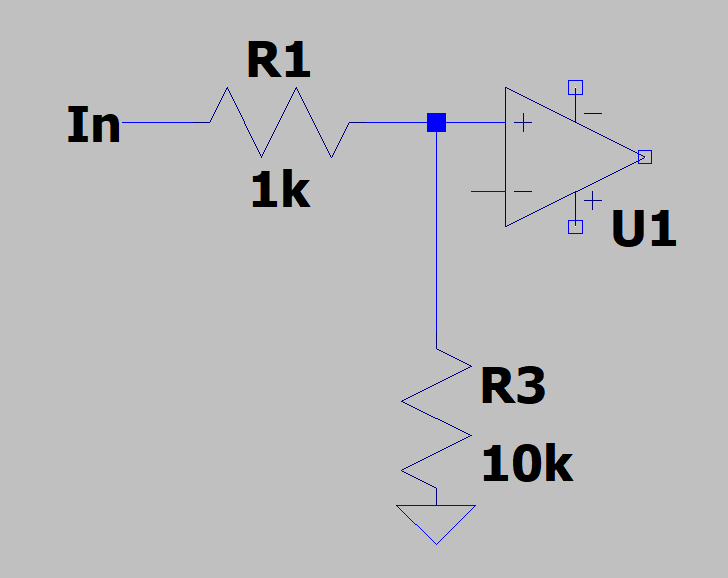
1. Assuming that this opamp is ideal (infinite ohms on input, 0 on output), why does the impedance not compound? With resistance, putting say two 1k resistors in series creates 2k worth of resistance - given the infinite impedance of the opamp, why is the impedance of this circuit not infinity + 1k?

2. Is impedance affected by only components in the signal path, or would the impedance of this be somewhere around 11k due to the 10k shunt to ground? I know it's a super basic question haha.

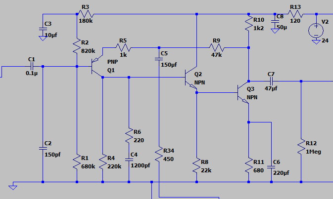
And finally 3, which is a bit more general: what determines the amount of impedance that can be driven by a given schematic? For example, I'm aware that something like the helios preamp below will struggle to drive a 600 ohm transformer, and there is an additional stage added to make that possible. Is this a function of the current in the circuit not being enough to push a load into the transformer?

agO1dal.png


Sorry for such basic questions, I'm very much a hands on learner and while my experimenting with audio circuits has gone swimmingly so far, I don't want to get ahead of myself, and figure clearing up some confusion on key topics is a good thing to do :)

Thanks! Ronan
 
Lerok said:
So, I think I have a fair understanding of impedance
Reading your question, I think not. You have still a long way to go.
You must understand Ohm and Kirchoff

My (very crude) impression is that input impedance is typically determined by the resistors used at Audio frequencies
That is very wrong. Capacitors (and inductors) play a big role in impedance.

Is impedance affected by only components in the signal path, or would the impedance of this be somewhere around 11k due to the 10k shunt to ground?
Figure out where current circulates. When it leaves the 1k, where does it go? It doesn't go to the opamp, because there is no current, as it's input impedance is infinite, so it must go into the 10k.

what determines the amount of impedance that can be driven by a given schematic? ... Is this a function of the current in the circuit not being enough to push a load into the transformer?
Yes, but many other factors come into account.
 
Hi Ronan,

Impedance is everything in E. If you understand the impedance characteristics of each of the 4 electronic devices: resistors, capacitors, magnetics (inductors, transformers, chokes, etc) and semiconductors (diodes, transistors, triacs, unijunction transistors, etc), then you will have a very good understanding of E.

Fortunately the concept of impedance is pretty simple and is just what it sounds like. It refers to how a device impedes the flow of electrons. If the terminal of a device is high impedance, electrons do not easily flow into or out of it. Low impedance would be electrons can easily flow.

However, the impedance at the terminal of a device depends on the properties of the device and it can also depend on the electrical conditions on other terminals. Let's take a quick run though each of the 4 types of E devices to get a better idea of what I mean:

1) Resistors. Resistors are easy because if the impedance at the other end of the resistor is 0, the impedance of it is just the resistor value.

Consider your 1K into op amp with 10K to ground. When talking about impedance, we're talking about the impedance at a "net". A "net" is some network of devices connected together. So "In" is a net, the intersection between the 1K, op amp + input and 10K is a net. Ground is also a net but it's impedance is assumed to be 0 for basic discussions.

So what is the impedance at net "In"? We there's only one device connected (in practice this would not be true of course!) so its' the impedance of the 1K in series with 10K in parallel with the op amp to ground. For basic discussions the impedance of the op amp is assumed to be infinite and again, ground is 0. So that just leaves 1K in series with 10K or 11K.

So what is the impedance at the intersection between 1K, the op amp + input and 10K? Well there's nothing at the other end of the 1K in your drawing so we have to pretend for now that it's infinite. And the op amp + is infinite. So that just leaves 10K to ground which is 0 which means the impedance is 10K.

However, in a real circuit the impedance on the other end of the 1K would not be infinite and therefore the impedance of the intersection net would not be 10K. But this is commonly overlooked because what we usually want to know about the impedance of a device is what it's "input impedance" is such that if we plugged something into it, would it be loaded or not. And so for this example, if we say were "looking into the input impedance" of this circuit, it would be 11K.

2) Capacitors. Capacitors are slightly more complicated because their impedance depends on frequency. At very low frequency, they are high impedance. In fact, at DC the impedance is infinite because no current flows at all. But at high frequency the impedance is very low. This is because the capacitor is like a really fast battery and it will just sink or source electrons immediately. If you have a capacitor that has no charge and you instantaneously put 1V across it, the initial voltage will be 0V but it will start to rise as it charges up eventually settling on 1V. How quickly it charges up depends on two things, the impedance of the source of current and the size of the capacitor. If you make the source a very low impedance but through a resistor of say 10K and a capacitor of 10nF, then you have a filter more commonly referred to as an RC filter. A high frequency voltage will just be completely absorbed by the capacitor where as low frequencies will pass. Meaning you have a low pass filter.

3) Magnetics. Magnetics can get very complicated with devices like transformers. But the simplest magnetic device is an inductor and an inductor is basically the inverse of a capacitor. When you instantaneously put 1V across it, the initial voltage will be 1V but it will start to drop as it the magnetic field builds up. If you take a 1H inductor and 10K resistor to ground, you again have a low pass filter.

4) Semiconductors. Semiconductors are too complicated to describe in one post but consider a diode. When the voltage across a diode is 0V, the impedance is very high. When it gets to about >= 0.6V (for a silicon diode anyway), the impedance is very low. And a transistor base emitter junction is basically a diode which is to say the impedance of a transistor is non trivial. In a circuit like your helios preamp, the circuit is designed so that the Vbe is very narrow. This is facilitated by something called "feedback". In other circuits like say a fuzz circuit, this may not be true. But if the Vbe junction is operated over a narrow "ohmic" region, then the input impedance of a conventional bipolar transistor is approximately the impedance of the net the emitter is connected to multiplied by the Hfe of the transistor which is usually between 100 and 400. So if the only part connected to the emitter is a 1K resistor for example, then you know the input impedance "looking into" the transistor base is going to be at least 100K-400K. But that's just the base. If there are other parts connected to the base you have to consider those to determine the true impedance of that "net".
 
abbey road d enfer said:
Reading your question, I think not. You have still a long way to go.
You must understand Ohm and Kirchoff
That is very wrong. Capacitors (and inductors) play a big role in impedance.
Figure out where current circulates. When it leaves the 1k, where does it go? It doesn't go to the opamp, because there is no current, as it's input impedance is infinite, so it must go into the 10k.
Yes, but many other factors come into account.

You're absolutely right - I know practically nothing when it comes to electronics, and I think I just misspoke, the more I read, the less I know, and while Doug self's books are great for application of ideas, I still regularly struggle with the theory.

As far as my understanding, it was based on readings from the internet (as currently that's the only resource I have available), so I apologize on that. I will spend some more time in the books and circle back around when I've had more time to really soak in as much information as possible.

Apologies :)

squarewave said:
Hi Ronan,

Impedance is everything in E. If you understand the impedance characteristics of each of the 4 electronic devices: resistors, capacitors, magnetics (inductors, transformers, chokes, etc) and semiconductors (diodes, transistors, triacs, unijunction transistors, etc), then you will have a very good understanding of E.

Fortunately the concept of impedance is pretty simple and is just what it sounds like. It refers to how a device impedes the flow of electrons. If the terminal of a device is high impedance, electrons do not easily flow into or out of it. Low impedance would be electrons can easily flow.

However, the impedance at the terminal of a device depends on the properties of the device and it can also depend on the electrical conditions on other terminals. Let's take a quick run though each of the 4 types of E devices to get a better idea of what I mean:

1) Resistors. Resistors are easy because if the impedance at the other end of the resistor is 0, the impedance of it is just the resistor value.

Consider your 1K into op amp with 10K to ground. When talking about impedance, we're talking about the impedance at a "net". A "net" is some network of devices connected together. So "In" is a net, the intersection between the 1K, op amp + input and 10K is a net. Ground is also a net but it's impedance is assumed to be 0 for basic discussions.

So what is the impedance at net "In"? We there's only one device connected (in practice this would not be true of course!) so its' the impedance of the 1K in series with 10K in parallel with the op amp to ground. For basic discussions the impedance of the op amp is assumed to be infinite and again, ground is 0. So that just leaves 1K in series with 10K or 11K.

So what is the impedance at the intersection between 1K, the op amp + input and 10K? Well there's nothing at the other end of the 1K in your drawing so we have to pretend for now that it's infinite. And the op amp + is infinite. So that just leaves 10K to ground which is 0 which means the impedance is 10K.

However, in a real circuit the impedance on the other end of the 1K would not be infinite and therefore the impedance of the intersection net would not be 10K. But this is commonly overlooked because what we usually want to know about the impedance of a device is what it's "input impedance" is such that if we plugged something into it, would it be loaded or not. And so for this example, if we say were "looking into the input impedance" of this circuit, it would be 11K.

2) Capacitors. Capacitors are slightly more complicated because their impedance depends on frequency. At very low frequency, they are high impedance. In fact, at DC the impedance is infinite because no current flows at all. But at high frequency the impedance is very low. This is because the capacitor is like a really fast battery and it will just sink or source electrons immediately. If you have a capacitor that has no charge and you instantaneously put 1V across it, the initial voltage will be 0V but it will start to rise as it charges up eventually settling on 1V. How quickly it charges up depends on two things, the impedance of the source of current and the size of the capacitor. If you make the source a very low impedance but through a resistor of say 10K and a capacitor of 10nF, then you have a filter more commonly referred to as an RC filter. A high frequency voltage will just be completely absorbed by the capacitor where as low frequencies will pass. Meaning you have a low pass filter.

3) Magnetics. Magnetics can get very complicated with devices like transformers. But the simplest magnetic device is an inductor and an inductor is basically the inverse of a capacitor. When you instantaneously put 1V across it, the initial voltage will be 1V but it will start to drop as it the magnetic field builds up. If you take a 1H inductor and 10K resistor to ground, you again have a low pass filter.

4) Semiconductors. Semiconductors are too complicated to describe in one post but consider a diode. When the voltage across a diode is 0V, the impedance is very high. When it gets to about >= 0.6V (for a silicon diode anyway), the impedance is very low. And a transistor base emitter junction is basically a diode which is to say the impedance of a transistor is non trivial. In a circuit like your helios preamp, the circuit is designed so that the Vbe is very narrow. This is facilitated by something called "feedback". In other circuits like say a fuzz circuit, this may not be true. But if the Vbe junction is operated over a narrow "ohmic" region, then the input impedance of a conventional bipolar transistor is approximately the impedance of the net the emitter is connected to multiplied by the Hfe of the transistor which is usually between 100 and 400. So if the only part connected to the emitter is a 1K resistor for example, then you know the input impedance "looking into" the transistor base is going to be at least 100K-400K. But that's just the base. If there are other parts connected to the base you have to consider those to determine the true impedance of that "net".

Thanks a ton, squarewave, I was really looking for direction on how to continue researching this, and this pointed me in the right direction - definitely have a lot to learn, but I'm optimistic!
 
Lerok said:
You're absolutely right - I know practically nothing when it comes to electronics, and I think I just misspoke, the more I read, the less I know, and while Doug self's books are great for application of ideas, I still regularly struggle with the theory.

As far as my understanding, it was based on readings from the internet (as currently that's the only resource I have available), so I apologize on that. I will spend some more time in the books and circle back around when I've had more time to really soak in as much information as possible.

Get/Read "The Art of Electronics" by Horowitz and Hill.
 
Lerok said:
the more I read, the less I know

Sometimes it wasn't until the 5th, 6th, or umpty-ninth read of a book that I grasped something, or that a light finally went on.

A lot of those books still make me groan when I see pages and pages of equations. 

Sometimes you need that space in-between filling your head with new concepts to go have fun tinkering with real parts and getting practical experience.  It all helps.


Winston O'Boogie said:
Sometimes it wasn't until the 5th, 6th, or umpty-ninth read of a book that I grasped something, or that a light finally went on.

A lot of those books still make me groan when I see pages and pages of equations. 

Sometimes you need that space in-between filling your head with new concepts to go have fun tinkering with real parts and getting practical experience.  It all helps.

Very True imo. The thing with "The Art of Electronics" is that it hits the right level between 'Hobby Electronics' and the very mathematical academic texts. Goes as easy as you can from basic components and parameters - RLC - to precison design criteria / mixed signal design / microprocessor / thru to (referencing my 2nd edition issue appendices) Butterworth Filter detail.
There is some 'Maths' (USA readers note the correct term :)) but it's kept in hand !
 
Hi Lerok -

Impedance is a tough nut to crack. I feel like I have been peeling the layers off for years and still don't really understand it. That being said, I'm not the sharpest knife in the drawer. Regardless, I find myself trying to find tutorials all the time on this stuff. There are a couple great Youtube channels that I follow. Some of it is way over my head, other stuff I pick up a little better. Here are a few:

RSD Academy
Mr. Carlson's Lab
EEV Blog

More guitar amp related channels I've used are: (This is where my entry point was and the videos form Uncle Doug on each part of a tube amp circuitry, the blocks and individual components was so important to my early understanding.)

Uncle Doug
D-Lab

Some books I found that helped were:

Boylestad - Introduction to circuit analysis
Merlin Belcowe's books on tube power supplies, guitar and bass amps and hifi
D. Self - Small Signal Amplifier Design
The RCA receiving tube manual
Crowhurst Basics
Briggs A to Z in audio

And the list goes on and on and on.

The more I work at this stuff the more I realize that you really can't skip any steps. I keep a number of binders at my house with notes. Some of them are broken down by subject. I keep one for general electronics, one for topics specific to solid state and one for topics specific to tube building and another still for power supplies. I keep well organized files on my computer with loads of newer and classic schematics plus ideas from this message board. Stuff that I can go back to repeatedly. When I'm working on a repair or a build, I keep files for those as well. What the problem may be, different things I've tried to resolve those problems and what my thinking was. I cringe sometimes at some of the ideas I had in my first few years, but I'm really excited now to look back at my obvious mistakes and realize I can see them now from what I've learned since then.

I'm 20 years since I did any real math other than counting to four or six. But I have a few books on that too and a friend who teaches math and is generally amused to know that I'm doing math at home for "fun." He's always willing to give me a hand when I am having trouble.

I can say that probably the greatest tool that I've had for all of this work is a wall mounted pencil sharpener. I know that we have all these high-tech tools now, but I'm a firm believer that a good place to start is with a pencil and pad of paper. Take notes. Re-write what you've learned over and over, from a book, youtube video, groupDIY thread or whatever else you're learning from. Then next time you sit down, try and write out those ideas, rules, theories and stuff from memory. Learn the passive components and simple circuits first.

There are heaps and heaps of books that are available online as PDFs or through your local library. Even the Art of Electronics that was mentioned earlier is available online as a pdf. (I am pretty sure this is legitimate too and that we're not ripping anyone off).

Most of all keep going. I like to think that we're all smart enough to understand this stuff (eventually) and the more folks that are working at it, the more we can help each other out.

I know this doesn't give you a quick answer to your question. But maybe some encouragement and place to start.

-

I found some parts of this helpful in direct relation to what you're talking about, on a very basic level but that's where we need to start.
 
"The Art of Electronics" sounds very interesting. I'm surprised I never heard of it before. And it's way more affordable than Doug Self's book "Small Signal Audio Design." (I keep threatening to treat myself to a copy of that...)
 
"The Art of Electronics" is currently selling on Ebay for around $20-25. And that's for hardcover.

Ok. But that sounds a little low. Realize that there are many different editions. I would be surprised if you find the regular 3rd edition for that. But the 2nd edition is great too if you're looking for a deal.
 
Beware that there are two vastly different books that share a common name.
One is the genuine Horowitz and Hill AoE, the other is a Student manual of the AoE, by Horowitz and Hayes, which makes sense only if you have the other book.
 
Good thing I didn't click the "Buy It Now" button! Looks like the one cheap one I saw was a first edition, and as Abbey pointed out, the rest were student manuals.

Gotta pay to play!
 
Actually, there are 5 books related to AofE:
- 1st edition
- 2nd edition
- 2nd edition Student book
- 3rd edition
- 3rd edition X files
(see pic, on right)

To be honest, the 1st edition of AofE is better than no edition, but beware of the student manual and X files.

Also, Self.

Neil
 

Attachments

  • bookshelf.jpg
    bookshelf.jpg
    167.9 KB · Views: 34
Go out and BUY TAOE, whether 2nd hand or new, 1st, 2nd or 3rd Edition.

It will take you from Ohm's Law to the highest level. When you become a true Electronics Guru in your old age, you will still be referring to it.

PS If you have the 1st or 2nd ed, you'll probably end up buying the 3rd ed too. :)
:sick::sick::sick:

I've mentioned this before, not a fan of AoE, I have the 2nd, 3rd and X-Chapters, they are all good books, but its just not my cup of tea. I appreciate its somehow simplicity, but I need numbers, equations, physics I don't like stuff like the "Transistor man" analogy to understand transistors, that is good for children, not for me, but to each his own.

It lacks a lot of theory, which for me actually makes a total beginner to be lost. The basics are barely covered, it won't make you an expert in electric circuits laws and analysis techniques.

However, I do like all the practical applications and stuff that is not covered in traditional college textbooks, but I completely disagree with the entire fan base and cult around the book, like if its the electronics gospel.

In my opinion, you should learn from something different first and afterwards you should read AoE

I do agree that the AoE should be required reading, but it shouldn't be your first book nor the authority...
 
I completely disagree with the entire fan base and cult around the book, like if its the electronics gospel.

In my opinion, you should learn from something different first and afterwards you should read AoE

I do agree that the AoE should be required reading, but it shouldn't be your first book nor the authority...
It's not the Gospel. It's a PRACTICAL book. The theory and eqns it has are those used by a practising engineer.

If you want to understand the circuits presented here or in Application Notes ... and perhaps venture into designing your own, I can't think of a better book to start or end with. Suggestions welcome.

As I said, you'll still be referring to it when you become a true guru in your old age so the expense won't be wasted.
 

Latest posts

Back
Top