The original 4K quad-bus GR-meter is a 1mA IIRC..
Jakob E.
Jakob E.


I think there is an image on Waynes site of the board configured as a GSSL meter which may help.
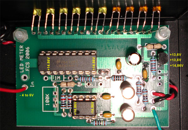
Yes you are correct in the above. Thanks for the annotated drawing - I'd like to use that.
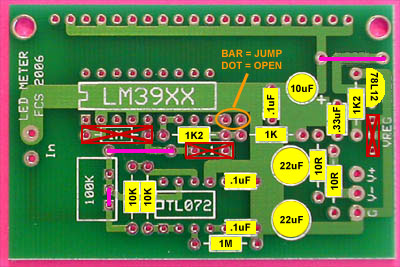
But, I think there needs to be a link across the trim pot terminals: The bottom two ones so the yellow 10K goes to the same point as the pink jumper. Electrically it goes from TL072 pin 7 to pin 6. (Would you mind adding a pink link there?)
I'm not sure where Roger grabbed his bipolar 15V but it was most likely from the main PCB or PSU. Since the LED currents are quite high in bar mode, I suggest referencing it all back to the PSU to minimize any voltage drops. You don't want the meter currents corrupting ground. I measured about 130 mA in bar mode all LEDs lit.
As to the GR line to the meter take a look at Gyraf's drawing where I zoomed in to the meter section. You are correct as to the general location, but I think you want the point before the meter's series resistor, not after. That resistor is for use with current meters, we want the GR voltage output at pin 8. This voltage goes more negative with increasing GR.
Thanks for the questions Matt you've obviously put a lot of thought into them and they are the same ones everyone else will have including myself. I've built the meter but for the Pico Compressor not using Ireg.
Not sure about why your power transformer center-tap is not connected to ground. I'd check that center-tap. Usually most bipolar supplies tie the center tap to ground. But, you want a sturdy ground at the regulators for the LED supply to the GR meter.
Your current drawing looks good but the 78L12 does need to be turned around.
Please add this to your drawing above the bar/dot link: Bar=Jmpr, Dot=Open and reverse the 78L12 so the flat side points to the LM3914.
Edit:
OK one thing jumped out at me already...
The lettering I C O next to the IREG should be O C I...
Or
O
C
I
matta;
Roger is correct. The device is oriented correctly - flat side to LM3914. But the text overlay is backwards. Sorry I didn't catch it.
But, I think the best thing to do is just remove the ICO overlay as the device orientation (being correct) makes it unnecessary.
Wayne
Matt
You mean the input of the meter?
If so, just remove the meter scaling resistor that used to feed the 1ma meter movement and connect the input pad on the LED meter to the GSSL pad that connects to pin 8 of the TL074. (Or put a jumper where the meter resistor used to go and use the normal pad)
The meter will get it's ground reference through it's power ground.
Once you get it all hooked up, check that you get FS deflection of the LED meter when you have -120mV on pin 3 of either audio path VCAs (NOT the sidechain VCA)
If for some reason you want a FS deflection at a different level than 20db GR, put in a trimpot on the meter board and adjust the gain feeding the meter to suit your application.
Have fun!
EDIT: Just checkd mine with an ohmmeter and the anodes are on the right (to the buss) and the flat side (cathode) to the left. So based on your description the LEDs are in backwards.
Enter your email address to join: