Vintage valve radio into valve guitar amp

GroupDIY Audio Forum

Help Support GroupDIY Audio Forum:

This site may earn a commission from merchant affiliate links, including eBay, Amazon, and others.
> hepgroove dynatode?

Time to go to bed.

Wash your hands! They used all sorts of strong chemicals in the old days, some later found to be more toxic than they thought. Plus whatever age-induced breakdown products in 60 years...
 
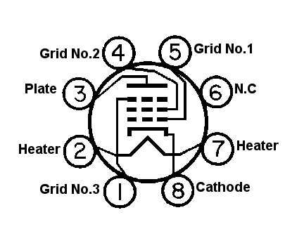
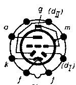
okay, I'm trying to figure our which pins are which on the diagram for the tubes.

http://www.r-type.org/exhib/aaa0702.htm

has the pin out numbers for the VP41. the rest can be found on that site also

but how do these correspond with whats on the diagram.

each of those three tubes look different and I dont know how to identify what is what. any help?? thanks
 
Here

From the bottom, they count clockwise from the index pin (if it has one)

Houston, I see a problem with feeding the grid cap of this tube. An open wire will hum. It may need shielding right up to the tube cap at guitar z's.
 
This is a random tube, used to show the internal elements, and their names:
micrex-L1-el34-tube-diagram.gif


So..their chart sez:

h= heater
k= cathode
a= anode (they mean plate)
g1= grid 1
g2 = grid 2
g3 = grid 3

and tc, i assumed meant "top cap"
 
if i've got this right then....

pins 1 & 8 are the heater on all 3. Pin 1 is ground, pin 8 is 13 volts from the transformer.

Using a a meter to test continuity pin 1 and 8 are showing as shorting on the chassis.. When they are disconnected from transformer they are ok. The transformer outputs however show as shorting. Is this just the low impedance of the coil. It was working before so I'm guessing here, but i just want to make sure.

Pin 2 is cathode, this goes to ground thru a resistor

i'll finish this later...
 
ok, so ....

VP41

pin 1 filament
pin 2 cathode
pin 3 plate/anode
pin 4 grid 2
pin 5 grid 3 (connected to cathode)

pin 6 - this one wasnt shown in the diagram. on the chassis it is grounded. the page on that website shows it as 'm' which is metalised

http://www.r-type.org/static/connect.htm

I guess this is ground then?

pin 7 blank
pin 8 heater

PEN45

1 & 8 filamnet
2 cathode
3 anode
4 grid 1
5 grid 2
6 grounded
7 empty

HL41DD

621.png


1 & 8 filament
2 cathode
3 anode
4 none
5 Diode 2
6 grounded
7 Didoe 1

TC = Grid

am I understanding this correctly, thanks
 
One more electrocution note -- well, two more. One guy at our TV station got zapped and very near killed; he was in the hospital for two-three days with his muscles in spasm. Not nice.

Me, the worst I ever took was about 300V from my finger to my lip -- yes, the ground was a microphone, and my finger strayed to the B+ through sheer stupidity. Hmm, that's the finger that can't pick as fast as the others. I wonder...

Anyway, it knocked me across the room. Took a while to recover. And I suspect that my 55-year-old heart would not have been as forgiving as my 30-year-old one was.

Peace,
Paul
 
thanks for all the warnings about high voltages. i'm being careful.

Can anyone tell me the value of C37? It looks like 8uf? It seems to be missing from the chassis. What voltage rating should it be if I am to get a new one? Also R13 and R14 are missing. Instead there is a single 57k(approx) resistor. Shall I reinstate these values?

If rewiring should I use single core or stranded?

Will an 8ohm speaker be okay on the output or should i strap a low value resistor across the output also?

thanks
 
Can anyone tell me the value of C37? It looks like 8uf? It seems to be missing from the chassis. What voltage rating should it be if I am to get a new one? Also R13 and R14 are missing. Instead there is a single 57k(approx) resistor. Shall I reinstate these values?

If rewiring should I use single core or stranded?

Will an 8ohm speaker be okay on the output or should i strap a low value resistor across the output also?

8uf. It may be a can. look for a wire somewhere to a can mounted cap.
I would reinstall that circuit because it will provide decoupling to the first stages. You want that. So redo R13 and 14 and put a 10ufd-35ufd 450v cap in there if that one is gone. Any wire is fine. 8 ohms is fine.
 
Like the guy said, any wire is fine, or at least will work fine. But I find solid-core to be a heck of a lot easier to work with in any place where it won't get repeatedly flexed.

I also generally like to use Teflon-insulated wire with tubed circuits just because of heat issues, but it helps that a local surplus dealer (Gateway Electronics) has Teflon wire in bulk for reasonably cheap.

Peace,
Paul
 
thanks guys! what kind of cap is that? it looks polarised on the diagram. Is it going to be an electrolytic?

I need to replace the shieled cable from R8 to V3, can I use coax TV ariel cable?


also about electric shocks. how can I ensure this will be safe when completed. It's for my brother and I dont want to kill him at his next gig!!

I'm guessing as long as everyting is earthed properly it should be safe.
 
yes, lytic.

i like the big blue LCR cans from

www.tubesandmore.com

like you see on the old marshalls.

hey, i see something new, click on "repro lytic box" those would be perfect for your old radio.

hmmm, no LCR, but the F & T looks like the same deal.
I like the clamp mounting aspect.
Go for the 50/50 at 500.

wait, they say JJ has replaced LCR.

is that the same as the tube company?

anyone ever use JJ filter caps?
 
hmm, that means waiting for them to land from the states.... I was gonna go down to maplins..

http://www.maplin.co.uk/Module.aspx?ModuleNo=12158&criteria=electrolytic%20450v&doy=11m3

these okay or 47uf too high?

or 2 of the 4.7 450volt ones?

http://www.maplin.co.uk/Search.aspx?criteria=VH21X&DOY=11m3
 
no probs, what about those values?

I've got some 13 amp mains cooker cable. this okay or will it introduce an impedance? It is thicker than the older cable i'm replacing, but it gives me red and black sleeved single core that I can cut up.
 
when you get that 47uf / 450 v, get a roll of 18 gauge solid wire.
We arent jump starting cars here. :razz:

also about electric shocks. how can I ensure this will be safe when completed. It's for my brother and I dont want to kill him at his next gig!!

Make a back cover with air holes. But if you observe the grounding instructions presented herein, you or your brother should be as safe as with any store-bought amp. Ground pin from wall socket connected to chassis, and also outer sleeve of guitar jack connected to chassis. If the first stage ever got a plate to grid short, I suppose it could send 250 or so volts up your kiver, cause of no coupling cap on the first stage. Ask PRR if you can add a cap there. He might say yes in this case.

I need to replace the shieled cable from R8 to V3, can I use coax TV ariel cable?
Something solderable, like a cannabalized rca cable wire. TV stuff is too ungainly. Also, use this shielded wire from the jack to the grid cap. Stop the shield an inch or so away from the cap. Ground the other end nearby.
 
lol, so about jump starting cars... the 2 x 4u7 would do? I dunno i'm just trying to find the quickest solution. I'm going to get the stuff in the morn, so want to get the right rating..

for casing I was planning to cut a big notch out of an old wooden gtr cab. its an empty HH VS musician. The original amps dead and is just a transistor thing, and theres no spkrs in it so i''ll stuff it with this and a couple of greenbacks eventualy.

Was going to leave the back open. theres a big gap at the top for the origianl head. this will fit with a bit of chiseling...2 spker underneath. should be enough ventilaltion if leave back off..??

at the min tho its only on a frame. will it need a metal enclosure around it
 

Latest posts

Back
Top