WE 407A Push-Pull Mic Preamp

GroupDIY Audio Forum

Help Support GroupDIY Audio Forum:

This site may earn a commission from merchant affiliate links, including eBay, Amazon, and others.
The 5116b has a small cap from cathode to cathode on first stage. Do not know what this is for.

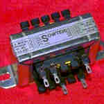
Sowter sells that Pultec output, S-217-D drop in.
Or load those suckers with a 670 output!
Has a feedback winding.
I have one and it sounds great.
Have to c heck henries. It handles two 12AU7's in push-pull.
Don't know if you want to spend real money on a prototype...

Whats a UTC 851?
Post your iron list!
 
Turn up the Impedance..Up..up up Turn up the Impedance..Up..up upTurn up the Impedance..Up..up upTurn up the Impedance..Up..up upTurn up the Impedance..Up..up upTurn up the Impedance..Up..up up

It's only 15k pri=(

jx150.jpg


8344 Fairchild Signal amp output
Sowter replacement design for Fairchild 670. 60kct/600ohms Ratio 9+9:1+1. M6 core in Mumetal can with colour coded leads. Size j
More info

Price: £53.93
8344 Fairchild Signal amp output
styleIj.jpg

On the other hand, I could use this and use one output side for fb (or is that illegal on split-bobbins?)
 
> 40 K , your killin me! Than God for the turns squared thing.

Twice as many turns of wire 70% the diameter.
 
Oh boy, there goes the dcr...
But max B gets divided by 4!
Still don't know hoew that works.
You would think the flux density would go up with turns.
Wait, if you keep same volts, turns go up, density has to come down. ok.


15 k is not bad.

weird, 670 sig outs used to come in a bell can
 
Ok, same circuit, with tertiary feedback gleaned from splitting an output secondary and using half for feedback, just to test the idea.
Seems to do the job. This is +10 dbm, a healthy pre-limiter level for a singer's peak.

Here's without the feedback winding:
nowinding.jpg


Unt Mit 10 db Feedback:
feedbackwinding.jpg

About a 10 db improvement. Funny how that works!

Sounds better when I yell.
A proper load on the output tubes will tell all. But the feedback works.
Noise floor seems less threatening, too. Not just cause I lost 10 db of gain, but it looks flatter. I bet this technique helps tune out some flaws in crappy iron. It certainly helped cutterheads.


Here's the schematic again:
FB.jpg
 
You could bias up the first tube and transformer with a resitor to ground, that way you can use positive volts to control the gain.
Darn, 4 pages, you almost nailed it in three, which would have been a record.

So do you like the more distorted version better, not that 0.5 is anything you could really hear...
 
Well, I just did an A-B and I like things about the higher THD non feedback (or less feedback) sound versus with FB in. The open loop had air and a more cartoony but good character. "Tubes" it said. Then I rewired the fb resistors and it was more accurate and flat and cleaner..you could hear that. (think Jensen. *Yawn*)I probably need a switch. By itself this thd flavour might be good. But with my Zero Feedback Fairchild clone downstream, it mite tire. We'll see. They both sound just kick ass. I cant shout with FB out tho. Gets a burr on it. New iron.
 
gong to double up core to get twice the impedance for same turns, still need more turns, maybe bump it to 12,000.

Current in wire means if i go over 40 ga, wire gets hot, and the winding windoiw is fixed, so can not add more turns because wir too thick.

The dual c core should prevent any overload.
 
chassis1.jpg

And I'm doing the chassis layout and shock mounting of my sub-chassis.
See those 2 screws on the top bracket? I wanna use rubber tubing on those inside as a shock mount to suspend the whole carridge.

I admire your Core Values.
 
Here's some pix of the final assembly: Wires on upper right are selectable mic impedances which go to a switch. So between the XLR and input transformer, I will have a 20 db pad, a polarity flip switch, and an impedance selector. I think I may bring out the feedback switch also.
final1.jpg

Here's a closeup of the preamp. Due to density, I guess this project went to "Skill: Intermediate", lol but it dosn't oscillate so I didnt want to find out how much bigger I could build it, Probably quite a lot. It does receive Ch 7, but snowy.
final2.jpg

Here is it's suave cover and shock suspension.
final3.jpg


Time to build the rest. Even tho the preamp itself is small, the peripheral connections are still significant!
 
[quote author="Larrchild"]
final2.jpg

[/quote]

Do I see a Solen and Orange Drop there?
Larry, you become way too fancy! Don't let audiofoolery catch you! :wink:

Wait a second... What about your Counterpoint? :shock:
You were supposed to make a line pre :green: :guinness: :guinness: :guinness:
 
Like I said, once I went differential, the iron to do that right became an issue.
So..After I box this up, I will build a one stage circuit with Lundahls on stem and stern. And an RIAA stage. Soon! :grin:
 
Nice! AM16 ish.
Whats the noise like?
I wonder if ac heaters are viable on this push pull deal.

OK, I double the core, take half the turns off the sec and I bump you up to 20K, sec indctance stays at 5 H..

If I add 1.414 times pri turns, we reach our 40 K.
Good thing dual coils, lots of turns = potential capacitance problem.

What is your percent feedback at the best gain setting?
Need to know turns for feedback winding.

Taps are available. Maybe I will build something with multiple taps so you can try different fb voltages.
 
Noise, subtracting the 60 hz from bad test gear hygene is around -95 below +4 (this is a +10 signal)
feedbackwinding.jpg

AC heaters might work ok. It has a balanced fil if ya wanna run 40v fils. You could adjust the cathode balance for min-hum. I'm using DC 'cause I have to make a nice 48 volt Phantom supply anyway.
I will use the resistor network to chose db's of feedback, so make it close to half of the 600 ohm winding's turns. Thats what I'm actually doing now.
I'm using 10 db of feedback. And I can't use more, or I will have a 30db preamp. I'm happy with 10db. It tamed it nicely.=)

In Marik's chosen photo, the 1.5 k resistors on the left are feedback adj.
Do I see a Solen and Orange Drop there?
From OCD HiFi Monthly:
"The aromatic body of the Solent was superior in the 1.2khz to 1.22 khz reigon and compared to the Left-Bank Panasonics *spits on ground*, the coloration was minimal."
 
I was thinking about this last night and realized that what we need is like a mic input that will handle 10-20 ma, and a lot of level!

If you reverse it, it's 600:40K, not unlike a tube input.
So, in order to keep dcr down, (otherwise we end upp with those plate resistors inside the transformer), I think we need some more perm.
No wonder all those 5116b's used to burn up.
Hall forgot about the resistive heat.
He has 12,000 turns on the pri!


So I an thinkin gapped 50/50 in 625 EI (too small) or 75 EI, which would be a honkin Neve output only in Nickel!

Gapped of course.
I could bobbin wind a bi-fi primary for good dcr balance and use Peerless 20-20 formula for coil structure.
We will see how this sounds and adjust from there.

Realize that we will have an 8:1 step down, whatever tyhat does to your 50 db I do not know.
 
So I figure if 10 db output level gives 3 volts, and we have a 1:8 (40 K:600), then the pri only has to swing 3 times 8 = 24 volts rms.

So you might be able to drop the B+ a bit?

Can you take a 1 khz measurement and see what your max plate to plate swing is when screaming into a U-67?


Thanks!
 
Right now, at full-steam, I have 20V rms @ 600 ohms on the output. 4:1 xfmr

So 80v x 1.414 = 113.2 P-P ac volts. But thats with the 27k's in.

Can't we use this extrapolation? Every time I put my scopes' ground clip on one plate, fire comes out.
Seriously, I'd have take a diff-input measurement to span the plates.
I guess I could use my DMM in AC.

133.2 volt swing is probably close.
 
OK great.
I gave Doc Hoyer a call becuase although I know some theory, I have never actually built a transformer based on anything more than a simple tuns calc and a gut feel for the core.

I learn a lot if I can keep him on track, but he has a ton of cool war stories related to audio, but you know how it goes......

"Lyman, when he was working for JPL, invented the split torroid...etc...etc..etc...for space missions so the transitors wouldn't pop.....the Langevine Leveline is beter than the 670, but nobody knows about it.....the Peerless K-241-D has the windings offset by 3/8 an inch....oh yeah, back to your transformer...."

I have a whole binder full of these precious tidbits!

Anyway, I think I got it all figured. You start from ther back.

And lets use 20 db, 10 db is too low.

so thats ten volts rms into 600.
an 8:1 makes it 80 rms = 114 volts peak = 228 p to p.
So your 250 B+ is perfect.

Now I can get B max.

But what frequency should I design for?
16 hertz is pretty common.
The core needs to double if we design for 8 hertz.

We try 16 and build it, then adjust later if needed.

Anyway, Michael Farady figured out that you need to move 100,000,000 lines of flux per second to make 1 volt rms.
10^8

so

B max = Volts sine wave rms times 10^8/4.44 times freq times Turns times cross section of core in cm^2.

so simplify constants along with 16 hertz and we have

Bmax = 1,407,000/Turns * Area

If you want a general formuala for B max based on 16 hertz you have

1,408,000 *E
------------------------
Turns * Core Cross Section (cm^2)

You can use that to figure out B max for any transformer you want to design.
Just use RMS volts that are going to be across the turns for variable "E".


Now we can make a chart with all differnt combos of turns and cross section that give B max to be whatever core material we use.

M6 = 18 k gauss
50/50 about 15 kGauss
Permalloy about 5 k gauss.

So I am developing the options for the core/coil assy as we speak.

Here comes the Boss.


:twisted:
 
if you design around 16 hz, you will have massive headroom at 100hz. like 8 db.

I was getting nearly +30 out of this thing. My 20v rms was based on that.

Just put a diode in series with it! (this is an obscure inside joke, folks)
 
30 db? Cool! These WE tubes are unreal.
I wonder what it would do with a 417-a in the driver's seat.

Luckily, we need more impedance, which means more turns, which means less B max, so we can do 30 db no sweat.

Did you measure your distortion figures after the transformer?
How much distortion do you want?
It is a function of B max as far as the xfmr is concerned.

Forgot about all the cool designer stuff in RDH4, so adding that to the recipe.

Doc says 7788 is another sleeper. )Tek scopes)
Never mind. $32.50 at Antique.
I guess word must have gotten out.
 

Latest posts

Back
Top