(yet more) Automotive design question...

GroupDIY Audio Forum

Help Support GroupDIY Audio Forum:

This site may earn a commission from merchant affiliate links, including eBay, Amazon, and others.

SSLtech

Well-known member
Joined
Jun 3, 2004
Messages
5,447
Location
Florida (Previously UK)
So the instrumentation illumination on one of my cars is lamentable. -Not just mine: it's a well-documentad design flaw in that model... -LOTS of complaints from owners.

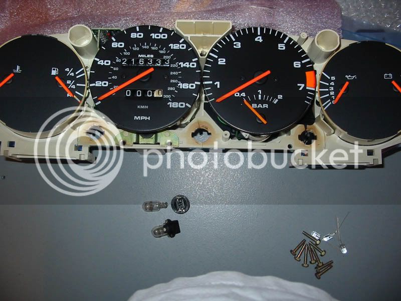
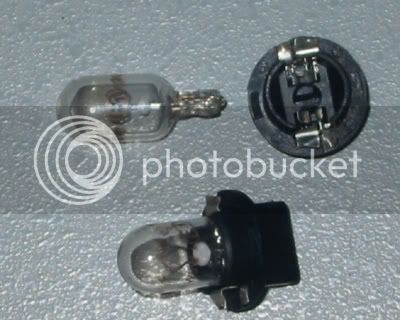
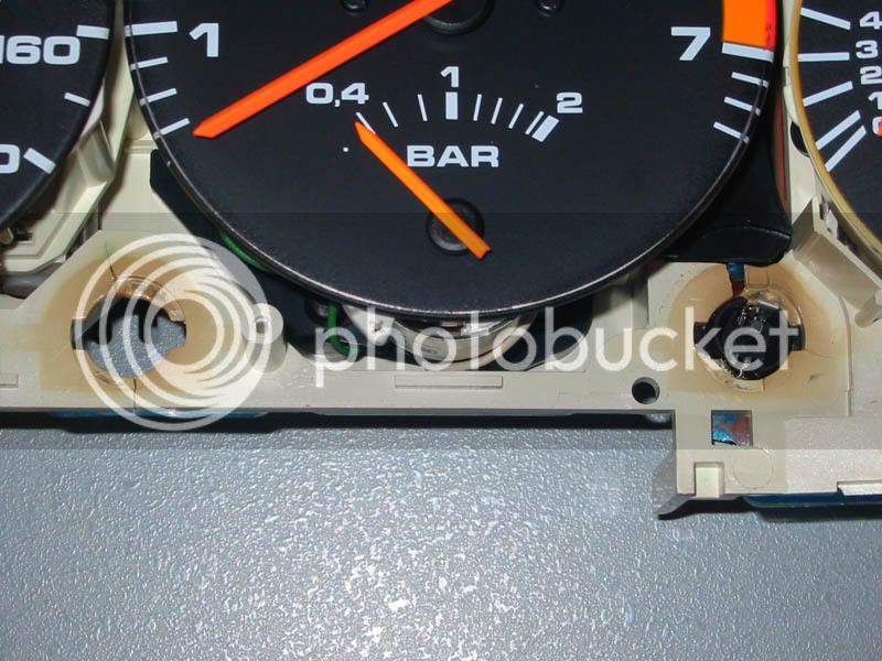
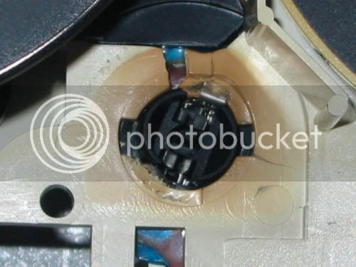
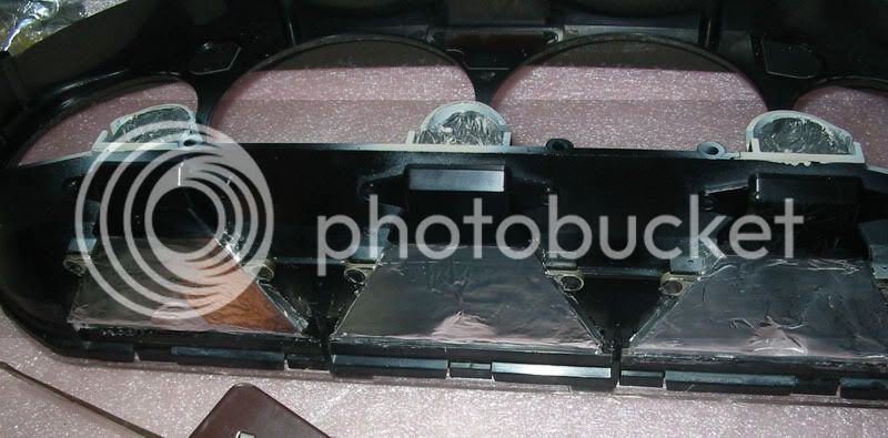
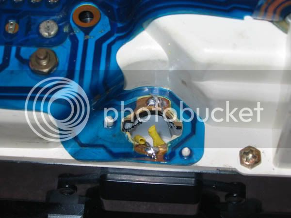
There are three 3-Watt bulbs in parallel, which shine down optic 'tunnels' and bounce back off the end to "hopefully" forelight the speedo, tacho, etc.

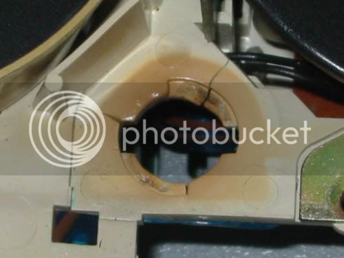
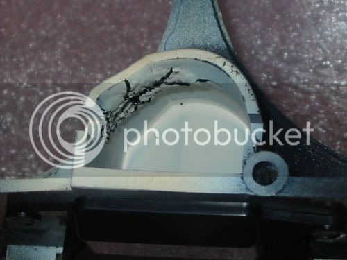
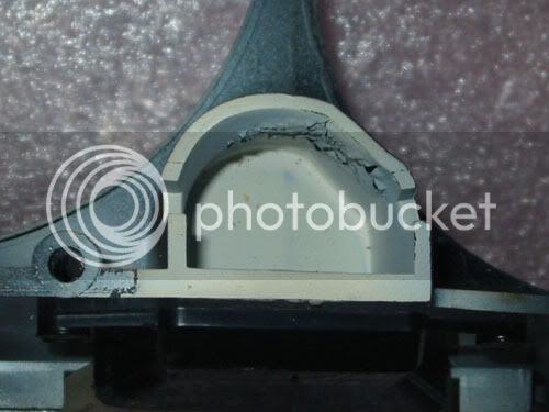
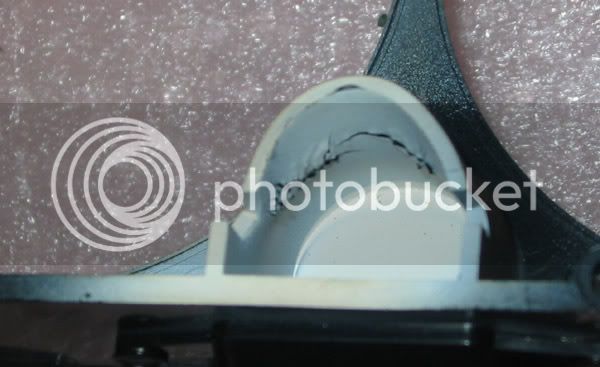
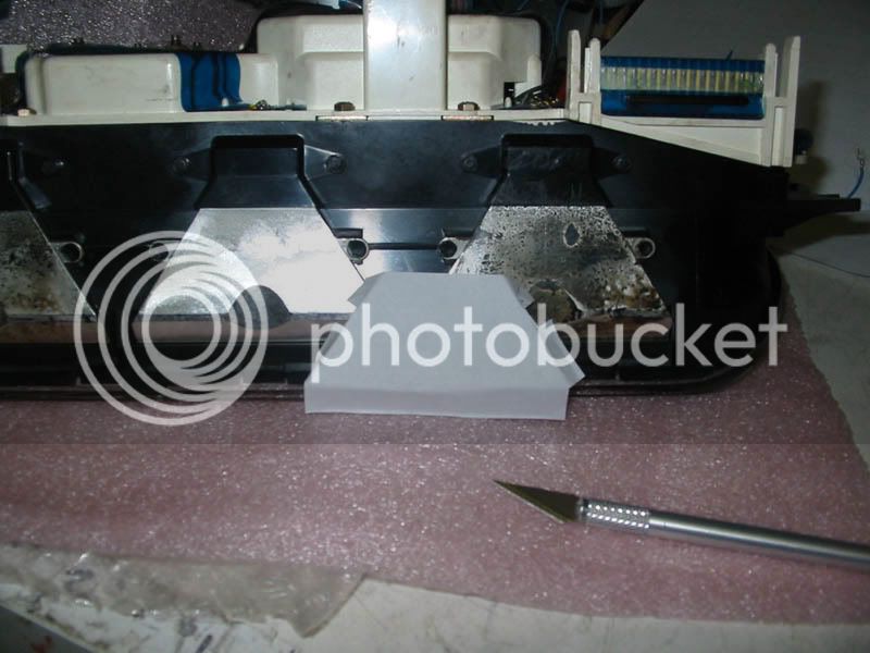
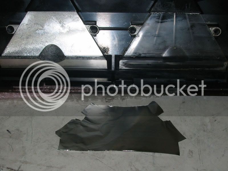
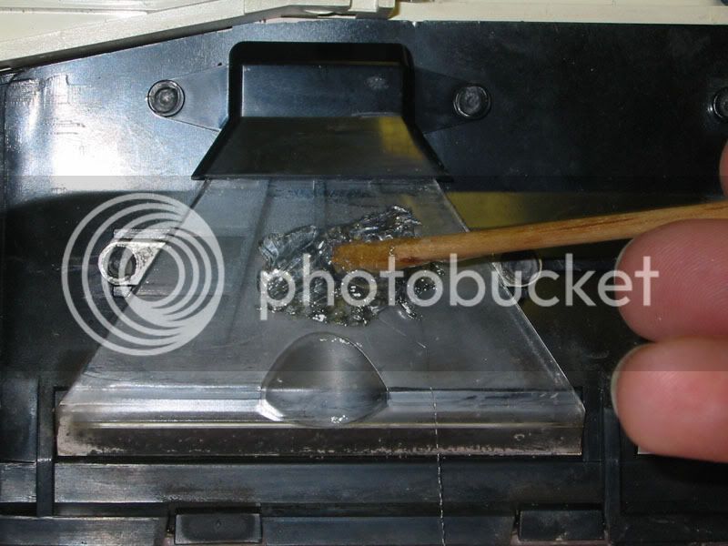
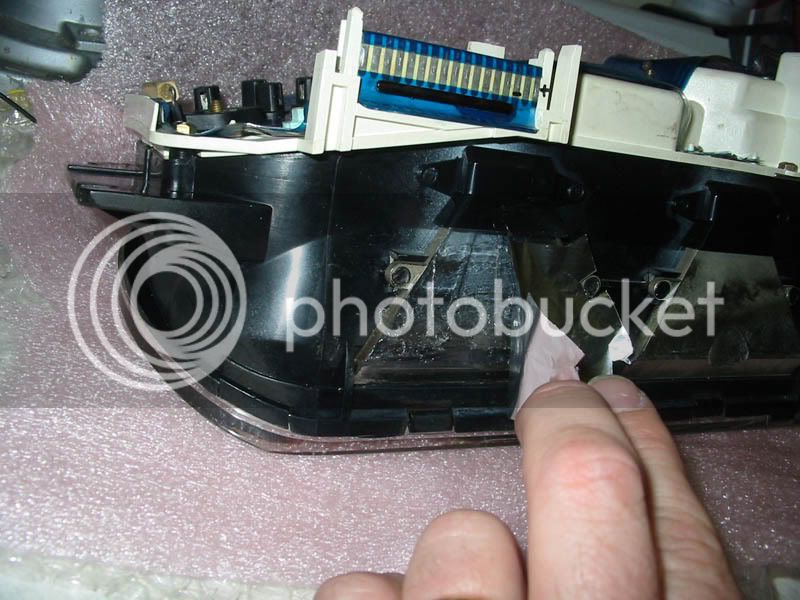
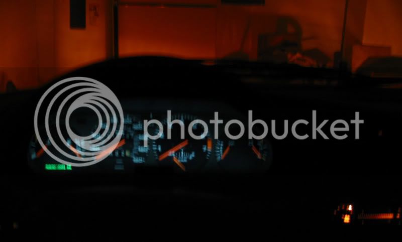
What happens is this: the 'silver' reflective coating on the light tunnels oxidises, and the illumination becomes very dim. Getting the dashboard apart is a pain in the a$$, so people tend to 'shotgun' the bulbs when one goes out, and they invariably put larger-wattage bulbs in there, to help with the dim illumination issue.

Over time, the three 5-watt bulbs which you ALWAYS find in there heat up and melt the bulb bases.

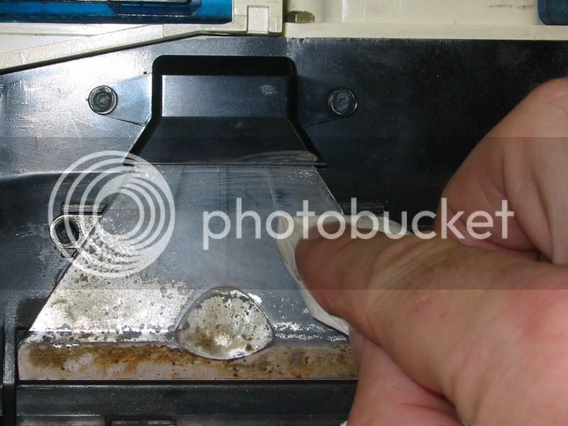
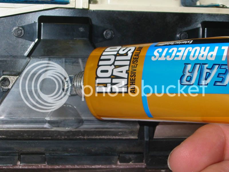
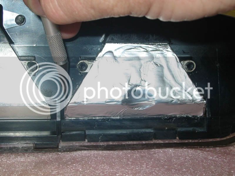
..So I replaced the bulbs with white LEDs (three clusters of four, in series pairs with two resistors per cluster), removed the silver with non-acetone nail-polish remover, re-silvered the tunnels with aluminium foil (shiny-side in!) and clear construction adhesive, then sealed the job with packing tape.

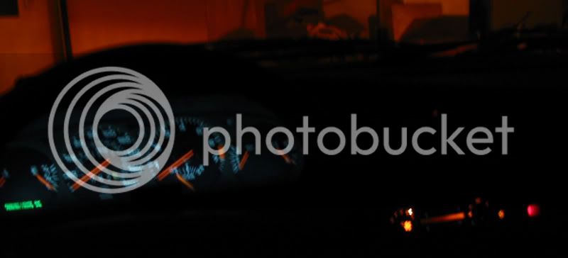
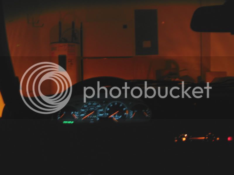
Result? -FABULOUS illumination! nice clear visibility (at times you couldn't even READ the two outer (voltage and temperature) gauges using the old incandescent bulbs. In addition, they now run cooler and won't melt the plastic (which the steady escalation of bulb wattage had begun to do!)

However...

Now that the current drain has been reduced from a couple of amps (three 5-watt bulbs for the cluster, plus all the other dash panel backlighting on the climate control, vent lights, etc. makes about 25 watts in total: 2A or so at 12V) down to a matter of a few milliamps, the dimmer (which is just a ~5-ohm -cold resistance- wirewound rheostat wired in series with the hot line of the illumination feed), the dimmer does absolutely nothing.

Not a massive deal, but there will likely be times when the light may be irritating and I'd like to dial it down a bit, whereas around twilight, I usually like to have the illumination set full-on, because it's quite 'shadowey' under the instrument panel 'shade', and my pupils are still often shrunk-down because of the sunlight at horizon level...

I COULD take a 5-ohm ceramic resistor and wire it in parallel with the dash lights, thus restoring the voltage drop at the wirewound rheostat, but that makes more heat and challenges my low-power ethics massively!

So, I'm trying to imagine a circuit which takes the 0~5 ohm (approx.) rheostat out of circuit, and somehow uses that to generate a voltage from about 5 to 13 volts or so... I can picture it using an op-amp and an emitter follower, but I wondered if there's not something simpler and more elegant, without resorting to op-ampery...

By the way, this is apparently a very common complaint, leading to the myth being spread around automotive fora that "LEDs can't be dimmed"...

Even my neighbour -who has a '65 Mustang convertible- when I told him that I was fed up and going to put LEDs in the dash illumination of my car, asked me "So, you presumably about the issue not being able to dim them?"

I'd love to prove them wrong! :wink:

Keith
 
One An adjustable constant current source. Look up the app note for the common 317. Maybe you can still use use the dimmer as part of the circuit

Two A low side switch PWM made from a a 555. I would use a mosfet or BJT as the driver.

Now with both you can add stuff to sense the headlights lights being on and switch in a different resistor etc to have two preset levels.
 
Can't use a low-side application, because the wiring is all direct-to-ground at several other (remote) locations...

Can't use CCS because of mixed LED/bulb combinations...

Keith
 
So now LED ground is going to be floating in an isolated circuit?

Or are you wanting a voltage regulator in series with the LEDs?
 
You can opto couple(float) a p channel mosfet high side to a 555 PWM,

Or use a PNP power transistor to the 555 for high side switching

Why not use a 317 on a heatsink to set the voltage
 
[quote author="beatpoet"]So now LED ground is going to be floating in an isolated circuit?

Or are you wanting a voltage regulator in series with the LEDs?[/quote]
..that was what I was thinking...

Keith
 
[quote author="Gus"]Why not use a 317 on a heatsink to set the voltage[/quote]
..Oooooohhhh... good idea... -I just have to 'translate' the resistance

Keith
 
To use 0-5 ohm rheostat to make 5-13V and not dump serious current, seems like at least a two transistor circuit.

The rheostat connects to +13 through a diode (for a .5v drop) and then to a pull down resistor to ground. This resistor is sized to give some small but usable variable voltage.

The junction of the rheostat and pull down connects to the base of a PNP. This serves as an inverting gain stage. The diode serves as first order correct for base emitter drop. Size emitter resistor (to +13) and collector resistor (to ground) to give usable voltage swing. Finally connect the base of a NPN emitter follower to the collector/resistor junction. The impedance of the sundry resistors will depend upon ultimate drive current needed.

======

Now for a KISS design perhaps trick up a 317, where you put the rheostat in the high leg of the voltage divider. The 5 ohm Rheostat in series with a 5 ohm fixed, and say a 47 ohm resistor to groud will give a usable adjustment range but dumping 250 mA at high brightness is 3W in 47 ohm.

You can put a diode in series with the rheostat to allow you to drop the current in half bit but now temp and current effects on the diode will degrade regulation (probably not an issue). This will let you scale up impedances to maybe the 1 W range.

Have fun

JR

(1.2v-.55V)/5 ohms= 110 mA or so....
 
[quote author="JohnRoberts"]The rheostat connects to +13 through a diode (for a .5v drop) and then to a pull down resistor to ground. This resistor is sized to give some small but usable variable voltage.

The junction of the rheostat and pull down connects to the base of a PNP. This serves as an inverting gain stage. The diode serves as first order correct for base emitter drop. Size emitter resistor (to +13) and collector resistor (to ground) to give usable voltage swing. Finally connect the base of a NPN emitter follower to the collector/resistor junction. The impedance of the sundry resistors will depend upon ultimate drive current needed.[/quote]
Me likey... elegant and simple math.

I'll try and rig one up this coming week. I would've replaced the rheostat with a usable pot if it were mechanically possible to do so, but I do want to keep it looking factory, and the mechanics are such that it's not really possible to change the guts out...
8287_1.JPG


Keith
 
> the instrumentation illumination on one of my cars is lamentable.

Don't lament. My Willys had a flashlight tucked in a hole in the seat cover. Also: if I put the cigar lighter through two cycles, and quick held it near the fuel gauge, I could read it. (Yeah, good glass gauge, not this plastic junk.)

> seems like at least a two transistor circuit.

If you need two, twenty is cheaper.

> Why not use a 317 on a heatsink to set the voltage

Zero resistance "should" give maximum voltage. That's not how the 317 thinks.

IF there is no legacy load on the dimmer reostat, and IF you can find an opamp with sufficient output current and to-plus-rail input compliance, this may be the minimum recipe:

6s65zk0.gif


R6 D1 are just serving suggestion, dummy LED array.

Ratios matter, not absolute values. But we are stuck with the on-board reostat. Trim R9 equal to reostat for full voltage range. If indeed you want a 4V-12V range, trim R9 to 7 or 8 ohms. So nail a 10R and shunt with a few 47R until the "full dim" is correct for moonless nights.

I was going to say we want low op-amp output stage drop from V+. However, you can maybe live with 10V if you fudge the LED resistors.

Cars can be harsh, 50V spikes etc. And since the reostat is hardwired to lightswitch and its surges, wiring Silicon via 5R resistor begs trouble. But it is a probabilistic worst-case problem. I bolted a 7805 to a gas gauge and it never failed. I know if I sold a million cars, some would come back fried. For Keith's play, I say just take a chance. Maybe socket the chip. Also, consider 1K from opamp "-" power leg to ground, with 0.1u cap across the chip to damp instability. This will limit pull-down, but you don't need deep pull-down. In a quick 60V spike, the whole chip will sit with 60V and 48V on its legs, feel only 12V abuse. This will rise, but nothing in a car will hold 50V for long. The old trick of 24V jump-start won't annoy a 36V chip. I would not build and sell a million without some Tesla-Tests, but hey: it's only an instrument panel and it IS Keith.
 
So here's a write-up account about how I went about improving the (eye-strainingly dim) instrumentation lighting, in case anyone's curious:

Here's what I was faced with:
Instruments.jpg


The instrument panel, with two of the three twist-out bulb holders removed. -The third one (on the far right) had actually MELTED the plastic to the point where I had to use LARGE pliers to twist it out... further breaking the plastic as I went. -You can see the other two holes (center and left) are also brown from the heat. The plastic was brittle and you can also see cracks there. None of the bulbs came out easily, but the one on the right put up a BIG fight.

Bulbs.jpg


An old bulb removed from the twist-base, and another one still installed in the twist-base.

A picture of the melted and cracked twist-lock bulb sockets:
Melt_1.jpg


...and a couple of gruesome close-ups...

Melt_2.jpg


Melt_3.jpg


In addition, the heat from the bulbs had done some collateral damage to the bulb 'shrouds' which form part of the front assembly:

Melt_6.jpg


...some more gruesome close-ups just for good measure...

Melt_4.jpg


Melt_5.jpg


Melt_8.jpg


The melting and brittleness of the plastic was caused by the use of higher-wattage bulbs (5 Watt bulbs in each of the three sockets) which creates a LOT more heat than the plastic can tolerate. The main reason for the higher wattage seemed to be the fact that the silver coating had degraded on most of the light 'tunnels'.

I elected to use aluminium foil to re-silver the tunnels, so I started by cutting out a basic template from paper, using an exacto-knife.

1_template.jpg


Then I cut out some (slightly-oversized) pieces of foil, to be attached "shiny-side-in".

2_foil-cutout.jpg


The old silver was removed using non-acetone nail polish remover:

remove-silver.jpg


...and some clear adhesive was added. -"Liquid nails" small-project adhesive worked great... had to be the CLEAR stuff though, -it also comes in a murky-brown version which isn't much good for this purpose!

Add-Adhesive.jpg


The adhesive was spread over the clear plastic on the bottom AND SIDES of the optic 'tunnel',

Spread-Adhesive.jpg


..then the foil was added. The adhesive went tacky fairly quickly, so I had the foil cut out and ready to be affixed BEFORE I spread the adhesive on.

Add-Foil.jpg


Then the foil was rubbed down using a ball of paper towel, and the edges were trimmed for neatness.

FoilFitted.jpg


Afterwards, I added some oversized pieces of clear packing tape, to protect the foil from any scraping which may happen while trying to wrestle it back into the dashboard. I let this overhang the edges of the silver, to provide more adhesion as well as protection.

Now... to further help 'gather' any stray light and reflect it into the optic 'tunnel', I decided to silver the inside of the little 'bulb shrouds' on the front lens:

Silver_2.jpg


Here's a close up of one:

Silver_1.jpg


LED retrofit:

My original intention had been to make something which would re-use the twist-bases, so that it could be swapped-in easily. The sheer heat damage to the plastic AND to the contact area on the flexible blue circuit board on the back of the instrument panel meant that this was probably not going to work as I'd hoped... The bulbs had been intermittent for some time (go over a bump and one goes out, hit a pothole and another one lights up... go over a railroad crossing and enjoy your own "intrument-cluster-disco"!) and this was probably down to the heat damage to the contacts on the rear circuit 'board'.

I decided that I'd have to solder. There really wasn't any other say to keep things reliable, and I don't want to have to pull the instrument cluster every time I have intermittent lights... I want this fixed once, and fixed right.

So by hooking the cluster up to the car, turning in the lights, and probing with the multimeter, I confirmed that ALL THREE light sockets have their positive terminal at the LOWER EDGE of the cluster... -Important with LEDs, since they can be damaged from being reversed.

-Revisiting this piscure for a moment:
Add-Foil.jpg


...you can see that I marked two contacts "+" and "-" on one of the connectors on the rear of the cluster (the horizontal connector behind the voltmeter/oil pressure gauges). The two terminals nearest the CENTER of the cluster are the terminals which connect to all three dashboard lights. That allowed me to test the dash illumination on the bench, by applying power, but -again- with LEDs it's important to know which to connect to positive and which to negative, so I marked them with a permanent marker for my reference.

I tried 2 x White 18,000mcd LEDs per bulb-location, running at 20mA nominal.

Here's some shots of how it was laid out:

LED-Join_2.jpg


The LEDs were popped through the hole, and bent so that they pointed DOWNWARDS to the rectangular hole at the entrance to the optic 'tunnel'.

Position_2.jpg


...a closer view:

Position_1.jpg


Around the back of the instrument cluster, you should be able to see how the leads were bent in order for the LEDs to 'sit' nicely against the 'window' into the optic 'tunnel'.

A word on what I discovered about soldering to the flexible circuit board contacts: If you ever have to do it...don't keep the iron in contact with the contacts on the PCB for more than a SECOND. If you overheat the circuit board, it starts to melt, and the traces can seperate... -Don't think that a cooler iron will be safer: a cooler iron will need to be held on longer. -If your iron has a temperature control, use it on a nice HIGH setting, and work quickly. put a small blob of solder on the middle of each solder contact and LET IT COOL for at least twenty seconds before going back and applying more heat... I found that if I worked PATIENTLY and I seemed to do no harm.

Solder.jpg


Once it was done, I bench-tested the illumination (as mentioned earlier), and since everything looked A-OK, I popped it back into the car.

Here's what the finished thing looks like in my car... VERY hard to take a picture that captures the illumination well, but here's a couple of (shaky, hand-held) 4-second exposures, in which I've tried to include the rest of the illumination (climate control etc... -still with the original incandescent bulbs... but not for long!!!) as a sort of light-level and color-temperature reference.

Finished_1.jpg


Finished_2.jpg


Finished_3.jpg


In the end, I used TWO double-LED chains per bulb location... because I actually like it pretty bright. They are wired in exactly the same way, just two identical series-chains of them through each hole.

I just love the fact that i can SEE the darned gauges at night, and that they don't flicker and flash like a techno-rave every time I run over the reflectors between lanes! :wink:

PRR, I like the idea: I'm going to try and sketch a similar circuit with a gain of 2, referenced to half-supply, and see if that works, just to avoid the "close to full supply at the inputs' thing that you mentioned. As long as the 'full-on' is within a volt or two of supply, I'm happy, so if the Op-amp doesn't want to do it all, I can probably stuff an emitter-follower on the output...

Keith
 
Keith if you do this again you might want to check Al foil tape for the light path. I think you can buy it a home depot and stores like that. I don't remember if the back is clear adhesive.
 
With regards to dimming, I'm a bit of a micro guy so I'd probably do something like this:

Microchip PIC (or something like it - I like the Freescale 68HC908 parts). Input scaled from 0-25 down to 0-5 volts via a voltage divider. Say, 33k2 and 10k. Run that to a 10-bit A-D converter channel. N-channel FET to connect a 100 ohm resistor to ground. Pulse for maybe 200 usec at 10 Hz. Low current draw = low heat. Measure voltage. Convert to duty cycle. Modulate output via a BTS432 high-side driver. To be fancy you can measure the +12 supply and ratio that with the output of the pot. Make sure to add filtering logic so that noise on the pot doesn't cause the annoying flicker.
 
nice job, low heat, now the dash wont catch fire.

nice write up also, i know how much work that is,

dimming led'S CAN BE FRUSTRATING!

I would rather be at the Led Zeplin concert, not the Led Dimmer show.

Is that neck wrenching, dust in the eyes work or what, i use to fix car stereos when you could remove hem without getting air bagged.

The log response is agravating, you have to use zero current to dim those things.

10 ma = brite
1 ma = medium
1 micro amp = dim,

well, maybe not that bad, but i always exagerate, so there.
sorry about the spelling on exagerate.
does scenario know you are doing this?

hey, check this Smart Car hitting a concrete wall at 70 mph:
that right vector is something else!
wickid whiplash.

http://www.youtube.com/watch?v=ju6t-yyoU8s
 
It did pretty well, but I would suspect the driver's internal organs would be pretty well smashed up after that kind of collision. Even if the car were tougher, the chances of survival would be around the same - very low.
 
I would use a PWM made on a single chip with a MOSFET driver.

Take one comparator with hysteresis loop, and one integrator. Feed an integrator from output of the comparator through the potentiometer with diodes connected from both sides to it's whipper; output from an integrator will go to input of the comparator. Turning a knob you change time constants between positive and negative phaseS of integration, so pulses on output of the comparator will go from shortest to widest. Apply this signal to a MOSFET that will regulate an average current through all your lightings.
You may use any dual opamp and HEXFET, low voltage one (such as 60V, some from IRFz SERIES) would be the best because of lower ON resistance that means less power dissipation.
If you want I can draw you a sketch of schematics that will work.
 
I'm OK with dc to dc for efficiency, but I'm also a fan of KISS. Who needs extra complexity (and RF energy) in a difficult, high reliability, environment. The lost energy from a pass regulator for this application is just not significant IMO.

JR
 
[quote author="JohnRoberts"]I'm OK with dc to dc for efficiency, but I'm also a fan of KISS. Who needs extra complexity (and RF energy) in a difficult, high reliability, environment. The lost energy from a pass regulator for this application is just not significant IMO.
[/quote]

>30 Hz (just enough for invisible blinking) does not mean too much HF energy, right? And few elements dissipating low power may be more reliable than one dissipating more.
 
Wavebourn Look at the earlier posts

It needs to be high side switching because of common grounds BUT SSL wants to use the existing rheostat.

In one of my posts I was thinking the rheostat could easily be changed to a pot some parts a 555 PWM and PNP high side switch without changing the look. The picture show otherwise

BJT could be better because the C to E voltage drop could be higher than a low Rdson power mosfet
 

Latest posts

Back
Top