SB4000 Support Thread

GroupDIY Audio Forum

Help Support GroupDIY Audio Forum:

This site may earn a commission from merchant affiliate links, including eBay, Amazon, and others.
etheory said:
Photos would be very useful however ;-)

Here are some photos of my transformer + mounting kit - I think it's pretty standard.

As I said, my main concern is whether it will be a problem if the top of the mounting washer touches the top of the chassis.

A Nylon bolt was mentioned which seems sensible - do you think this will be strong enough to hold the transformer in place?

Many thanks for your help!
 

Attachments

  • both.JPG
    both.JPG
    310.9 KB · Views: 44
sdrjones said:
A Nylon bolt was mentioned which seems sensible - do you think this will be strong enough to hold the transformer in place?

It's very strong. I've never had a problem with them in any of my builds. Of course I'm not knocking my equipment around or dropping anything to test that out, but if you epoxy it well like I mentioned then it's more than strong enough for normal use and carting around.
 
I could use some varification here:

Internal sidechain and compressor button wiring question.

I have the anode and cathode wired up to respective + and - on the switches. I have Common from board going to C1 on switch and N/O going to NO1 on the switch, NC1 on the switch is vacant.

Is this correct?

Cheers,
Chris

 
sdrjones said:
etheory said:
Photos would be very useful however ;-)

Here are some photos of my transformer + mounting kit - I think it's pretty standard.

As I said, my main concern is whether it will be a problem if the top of the mounting washer touches the top of the chassis.

A Nylon bolt was mentioned which seems sensible - do you think this will be strong enough to hold the transformer in place?

Many thanks for your help!

mine is definitely hitting the top of par metal chassis. I am about to start wiring. I'll let you know if the bolt hitting the chassis is an issue.
 
buildafriend said:
sdrjones said:
etheory said:
Photos would be very useful however ;-)

Here are some photos of my transformer + mounting kit - I think it's pretty standard.

As I said, my main concern is whether it will be a problem if the top of the mounting washer touches the top of the chassis.

A Nylon bolt was mentioned which seems sensible - do you think this will be strong enough to hold the transformer in place?

Many thanks for your help!

mine is definitely hitting the top of par metal chassis. I am about to start wiring. I'll let you know if the bolt hitting the chassis is an issue.
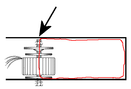
You don't want a conducting bolt touch the top of a conducting case. This will make a (unfortunately shorted) single turns secondary winding and fry the primary winding of your toroidal transformer that cannot deliver the current demand of this shorted secondary winding. With a little luck your mains fuse will blow faster.
Just cut the bolt to the min.required length. Maybe glue some insulating material to the top of your case to play safer.
Toroid_mounting.gif
 
Thanks Harpo, you beat me to it.  This is why I use DMD on top of my enclosure above the toroid (believed mentioned somewhere ealier in the thread)
 
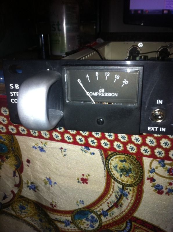
Well, guys, reporting in after several months of using this unit. I have to say it is the piece of equipment I am most proud to own. I use it on master buss for virtually every mix I do.

If you'd like to hear what it sounds like, most of my work ends up on http://youtube.com/thealternateside907 and /wfuvradio. Or on my blog at audiodork.com. Built it, love it, will build another.

Thanks ruckus!
 
DanH said:
If you'd like to hear what it sounds like, most of my work ends up on http://youtube.com/thealternateside907 and /wfuvradio. Or on my blog at audiodork.com. Built it, love it, will build another.

Thanks ruckus!

Hey Dan,
Nice Music! Awesome!
cheers,
 
Yeah, man good job!  I built two myself, one for drum squishing madness and the other for the output bus.  Cant go wrong man... doooo eeeeet!!! get another!!!
 
Thank you very much for the advice, that saved me a lot of time!

Where can I find an appropriate bolt for the power xfrmr? or what should I use as an insulator on top of the chassis?

Also, Which one of these pins are the kathode, Anode, hot, and cold, connectors?
b4da8331.jpg

4f97de4e.jpg
 
I built this a while ago, but remember facing the same question. If I'm not mistaken, you can test for anode/cathode by applying DC since current can only flow in one direction.

Also guys I made a video demoing my SB4k on drums. Check it out here if you're wondering what it sounds like!

sb4000-video-featured1.png
 
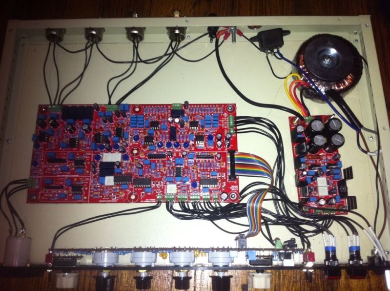
alright so i finally got this thing wired up. I left the top off to avoid needing any kind of special bolt for the psu xfrmr or insulator for the chassis. it powers on without issues and i was about to start calibrating the L/R balance when i realized that when the compress button is engaged all i hear is a low freq hum that could very easily be a ground hum. I could use some advice as to how to trouble shoot this. I remember reading that there are two main board ground points that must be connected and go to the star ground point, I am not 100 percent sure I connected them. I can not wait to have this thing going! .. my first master buss compressor, its so exciting!!
 
Just dont cut the black wire.....  ;D

On a serious note... Thats a real clean lookin build man, would have liked to have that extra space in the case for mine, but i was lazy and just bought the case from ptown, kinda tight, but worked great. 

1) are you using the triad transformer?
2) if so...are you wiring for 240?  (if yes disregard this post)
3) if YES to #1 and NO to #2, the transformer wiring doesn't look right for 120. My TX has the blue and purple wires together going to the on/off switch and the grey and brown together going to the IEC.

Also, Ruck, would you mind if I sent my build to a reputable commercial studio for use in an official shootout between yours, SSL's and some other 3rd party's poor excuse for an SSL clone (ive seen it and looks like ARSE!)? I accidentally rubbed it in someones face that yours had the HPF and internal side chain build in, without need for modding, started a bit of a war lol.
 
@buildafriend, some remarks.
1) Mains fuse seems missing.
2) From your profile location info you seem to be US based, so the mains transformer primary windings will be wired in parallel for 120VAC mains. Your pic seems to show the primary windings hooked up in series for 230VAC mains. This will hum, because the transformer now only transforms to half of its secondary voltages. Not enough for your PSUs regulators.
3) A toroidal transformer for usual radiates the largest field where the leads come in/out. You might twistturn it about 180 degrees, so leads are closest to your case corner. Distance is your friend.
4) Twist each pair of at least your audio-In hot/cold wires, so the balanced line receiver has a chance to cancel out common mode induced garbage.
5) Missing resistors at the audio-VCAs?
 
sr1200 said:
Just dont cut the black wire.....  ;D

On a serious note... Thats a real clean lookin build man, would have liked to have that extra space in the case for mine, but i was lazy and just bought the case from ptown, kinda tight, but worked great. 

1) are you using the triad transformer?
2) if so...are you wiring for 240?  (if yes disregard this post)
3) if YES to #1 and NO to #2, the transformer wiring doesn't look right for 120. My TX has the blue and purple wires together going to the on/off switch and the grey and brown together going to the IEC.

Also, Ruck, would you mind if I sent my build to a reputable commercial studio for use in an official shootout between yours, SSL's and some other 3rd party's poor excuse for an SSL clone (ive seen it and looks like ARSE!)? I accidentally rubbed it in someones face that yours had the HPF and internal side chain build in, without need for modding, started a bit of a war lol.

haha what do you mean? this thing is all color coded.

1) I am using a triad ( I believe? ) It's this xfrmr

http://www.mouser.com/ProductDetail/Triad-Magnetics/VPT36-1390/?qs=wkKrz7WmEgM2EIrgD3Tzhw%3d%3d

2) I am wiring for 120

3) Ohhh.... that might help! Are you in america too?
 
Harpo said:
@buildafriend, some remarks.
1) Mains fuse seems missing.
2) From your profile location info you seem to be US based, so the mains transformer primary windings will be wired in parallel for 120VAC mains. Your pic seems to show the primary windings hooked up in series for 230VAC mains. This will hum, because the transformer now only transforms to half of its secondary voltages. Not enough for your PSUs regulators.
3) A toroidal transformer for usual radiates the largest field where the leads come in/out. You might twistturn it about 180 degrees, so leads are closest to your case corner. Distance is your friend.
4) Twist each pair of at least your audio-In hot/cold wires, so the balanced line receiver has a chance to cancel out common mode induced garbage.
5) Missing resistors at the audio-VCAs?

All remarks and advice are appreciated
1) I don't know where the fuse should be in the circuit. Maybe on the hot wire of the primary of the power xfrmr? as you can see I have a fuse that is separate from IEC connector. I am not sure where it should be connected.
2) Do you mean the mains transformer primary windings on the positive side(the primaries with the dots)? If anyone could rig together a fast wiring diagram it would be a huge help. It seems the one I used earlier in this thread is not for the US.
3) Thanks! Will do!
4) Hm.. I never knew that helped cancel anything out. Does that even matter though since this is an unbalanced circuit? I mean I'll do it, it seems to be something that everyone is doing. I bet they are doing that for a reason.
5) Oh it says not to throw those in somewhere in the build guide. Certain resistors on this board are only for use with certain chips. The board also accepts the original gold and black can DBX VCA's

Wow I just learned a lot.
 
buildafriend said:
Harpo said:
@buildafriend, some remarks.
1) Mains fuse seems missing.
2) From your profile location info you seem to be US based, so the mains transformer primary windings will be wired in parallel for 120VAC mains. Your pic seems to show the primary windings hooked up in series for 230VAC mains. This will hum, because the transformer now only transforms to half of its secondary voltages. Not enough for your PSUs regulators.
3) A toroidal transformer for usual radiates the largest field where the leads come in/out. You might twistturn it about 180 degrees, so leads are closest to your case corner. Distance is your friend.
4) Twist each pair of at least your audio-In hot/cold wires, so the balanced line receiver has a chance to cancel out common mode induced garbage.
5) Missing resistors at the audio-VCAs?

All remarks and advice are appreciated
1) I don't know where the fuse should be in the circuit. Maybe on the hot wire of the primary of the power xfrmr? as you can see I have a fuse that is separate from IEC connector. I am not sure where it should be connected.
2) Do you mean the mains transformer primary windings on the positive side(the primaries with the dots)? If anyone could rig together a fast wiring diagram it would be a huge help. It seems the one I used earlier in this thread is not for the US.
3) Thanks! Will do!
4) Hm.. I never knew that helped cancel anything out. Does that even matter though since this is an unbalanced circuit? I mean I'll do it, it seems to be something that everyone is doing. I bet they are doing that for a reason.
5) Oh it says not to throw those in somewhere in the build guide. Certain resistors on this board are only for use with certain chips. The board also accepts the original gold and black can DBX VCA's

Wow I just learned a lot.

Harpo, if you have anything to add please be my guest, but:

1)  Fuse should always go between line (L) on the IEC and the Power Switch.  Power switch is then wired to transformer primary.

2)  Your transformer will come with an instruction sheet of how it gets wired for 120V or 240V.  For 120V, you want to wire the transformer primaries in parallel.  For the VPT36-1390 transformer only - this means tie Blue/Violet together, and tie Gray/Brown together.  Blue/Violet is you Hot, and gets connected to your fuse.  Gray/Brown is your Neutral, and should be connected to Neutral (N) on your IEC.

4) It's done for the reason Harpo already explained. This is a balanced circuit, it's not unbalanced.  If you plug in an unbalanced connection on the output it will load down the 5532 output chip, eventually probably killing it.

5) Nowhere that I know of.  Those two resistors need to be installed for THAT218X chips, otherwise no compression or makeup gain will be possible.
 
Back
Top