newbie builds ioaudio MK47 microphone

GroupDIY Audio Forum

Help Support GroupDIY Audio Forum:

This site may earn a commission from merchant affiliate links, including eBay, Amazon, and others.
maq3396 said:
Okay....almost finished this build but...cannot figure out if there is supposed to be an internal switch for testing when one uses Zayance's pcb. I have been through the entire build section as well as this one. I only see the pattern selector switch and the trim pot for the 105V out.
Is the switch only there if the resistors for testing are built into the board (as shown on page 3)?
Thanks
Mac

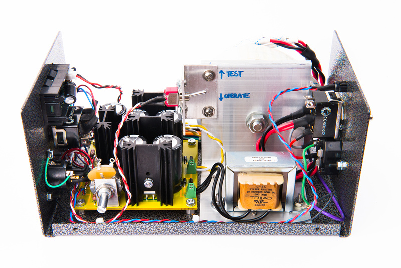
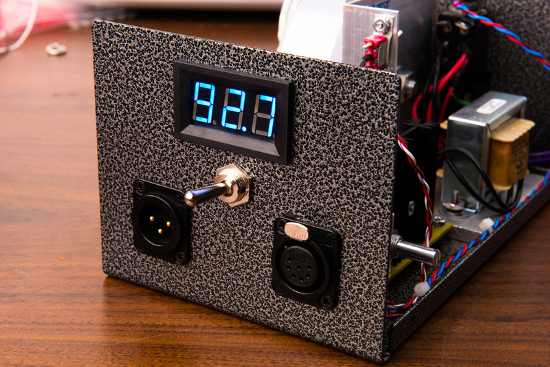
If you look over the build again, you will see that there is no test resistor on the Zayance PCB as it is essentially used only once.  I have a photo where I strapped a resistor between B+ and Ground on the screw terminal to set my initial voltage.
 
Hey Chunger, here's my P2P thanks for your inspiration to pull this off.  Was my first turret board.  I had first your layout for this project, soon found it wouldn't fit so I had to massage some things to work with the Collective Case.  Most wiring is under board.  The mic sounds fantastic!

5s7l.jpg

08u4.jpg


And here's how I implemented the 'dummy load'.

dpiz.jpg

jmy7.jpg
 
Thanks Chunger,

Just wanted to make sure I wasn't missing something too obvious!

Cheers
Mac
 
The mk47 with the Chinese 35mm k67 has a bit of bite, but it worked out really well.  I have tskguy's K47 and Beesneez M7 and K7 to try, but am waiting for the gen. 2 GT-2B bodies to arrive before putting those together.  The guys at the studio want to keep the Chinese capsule version as is for now.
 
I don't want to be lazy, but does somebody have an order list from Mouser for the Powersupply components?
Would really help. thnx
 
I live in the Netherlands, power here is 220/230.
Been looking at this forum lately to get components for my PSU, but I did not know there are 2 versions.
I have the electronics of Max, the iaudio 47 circuit with the 2 parallel tubes.

Would help so much if somebody could give me a guide on what PSU circuit I need to build including components.
It is my last step in completing the project :)
 
Hi there:
I'm built the mk47 PSU with zayance PCB, i have some doubt with the pattern selector (cardio / omni)
Why in Cardioid mode the pattern terminal is reading 0V, and in Omni mode is 105V?.

Regards
 
rodcaster said:
Hi there:
I'm built the mk47 PSU with zayance PCB, i have some doubt with the pattern selector (cardio / omni)
Why in Cardioid mode the pattern terminal is reading 0V, and in Omni mode is 105V?.

Regards

It will only show the correct pattern voltage with either the mike attached or a test 12k resistor standing in for the relay coil.
 
Prototyping an mk47 PSU on a PCB/BOM designed by Matador with the aim of providing an all-inclusive kit for the build.  We still have to make a few revisions on the design and this is prototype (not final) metalwork.  This build is just to lay everything out and get our feature set into an actual device to see how it all works.  We are using the Antek 200V 50VA toroid in this build which is quite large and has extra 6.3V secondaries that this design does not use.

I am thinking about stepping it back to the 230V triad for cost and weight.

key features:

- direct implementation of Max's original schematic
- robust heatsinked resistors
- built-in voltmeter
- external B+ trim adjustment

p1020436100-4.jpg


p685702534-4.jpg


p754697114-4.jpg


p365000824-4.jpg


p480731709-4.jpg


p1054008336-4.jpg


p881130931-4.jpg
 
chunger said:
ok. . . onward.  Next I go for the back side of the PSU case with the power switch and IEC power jack.

p702750369-4.jpg

Hi chunger. I'm nearly done building your point to point power supply and realized I never ordered the mains power switch. Can you share the part number of the nice one you used?

Cheers!
 

Latest posts

Back
Top