chunger
Well-known member
A small update. . . I've mostly been hacking metal to build the rev. 3 PCB prototype. We still have a few minor tweaks to do on the board, but for the most part, it is very close. I think if I don't run into any MAJOR malfunctions, we will be able to move to full production PCB while implementing the very small adjustments.
My main purpose for this prototype build is to test function with the lower-cost, smaller, lighter, more readily available Triad 230V 25VA transformer that I had used on my 1st 2 builds on this thread. We will make sure the final case design fits the 200V Antec with the 6.3V taps because we do have plans to use the same case configuration and standoff locations to implement some of the other PSU designs for various microphones. I also want to nail down a final BOM for the 230V transformer since many of the values shift when the voltmeter is introduced into the passive PSU topology. These low-cost Chinese meters do not come with any documentation so it takes a little bit of experimentation to figure out the right resistor values.
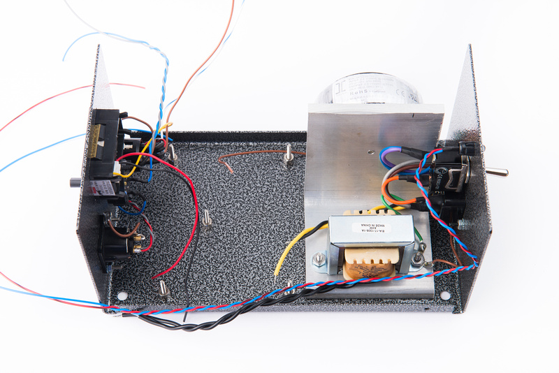
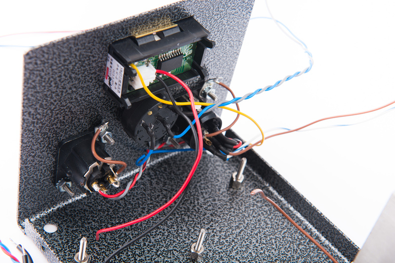
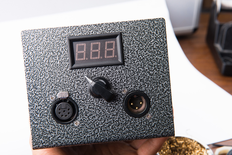
I cut a 3" piece of aluminum L-bracket to mount my toroid and choke. Holes were drilled and tapped to install this L-bracket. I also cut a hole in the front face for a digital voltmeter as well as a 3/8" hole for the rotary pattern switch that I like to use. As I was merrily building, I remembered that Matador wanted detailed updates on the prototyping process because he usually does this stuff and doesn't have his workshop set up yet, so I brought out my camera and started properly documenting.
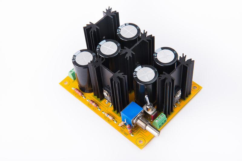
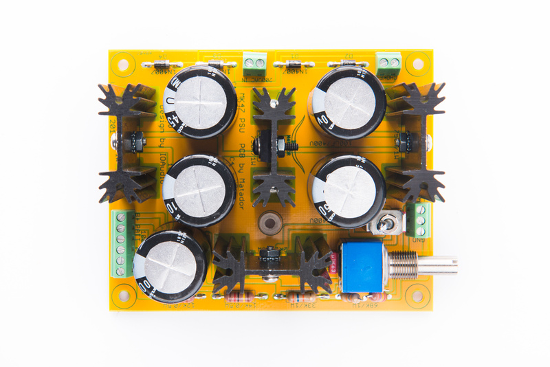
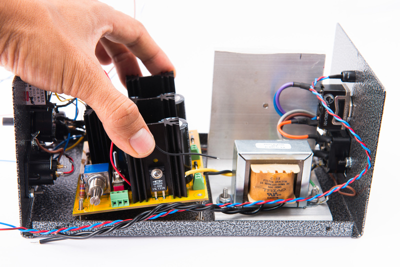
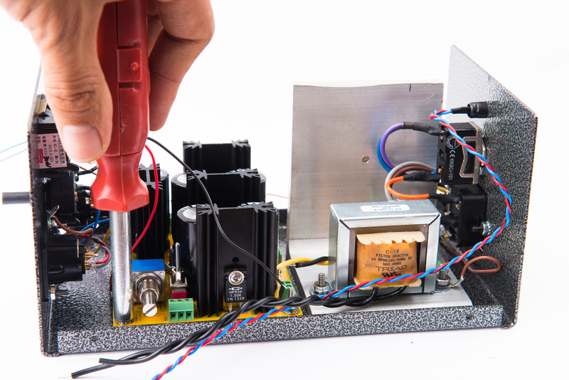
One of the most critical PCB positioning considerations is the attenuator pot which is now directly PCB mounted on the 3rd rev. board.
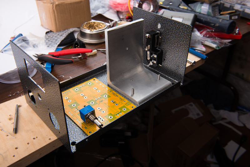
The end of the pot needs to sit nearly flush with the outside case so a screwdriver can be used to adjust B+ externally, but the screwdriver will not be able to enter the case by accident.
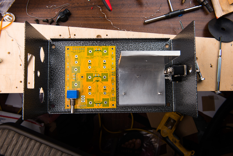
Some may find this method a bit crude, but I clamp and use the actual PCB as a drilling template so my standoff holes are exact. I know this board will fit with 100% certainty.
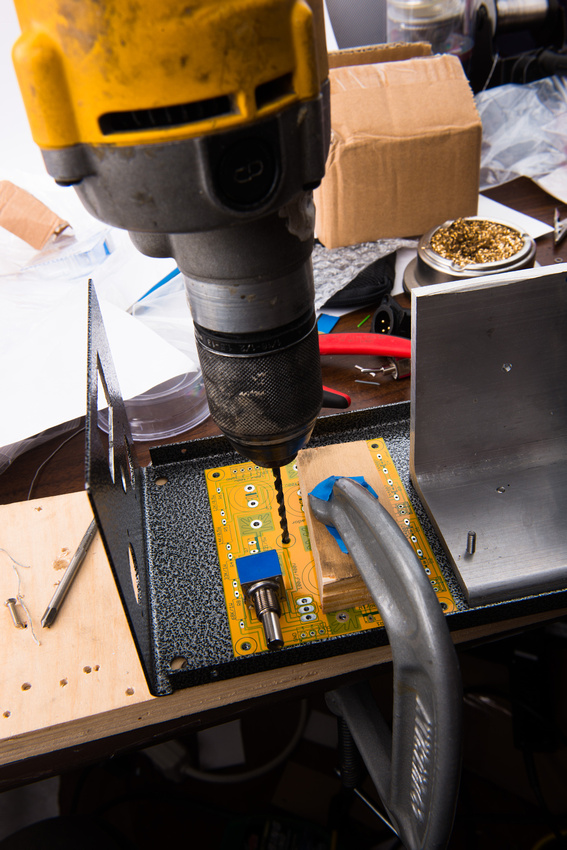
Once the holes are drilled and chamfered on the back side for flat head screws, I install my standoffs.
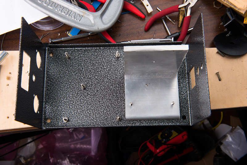
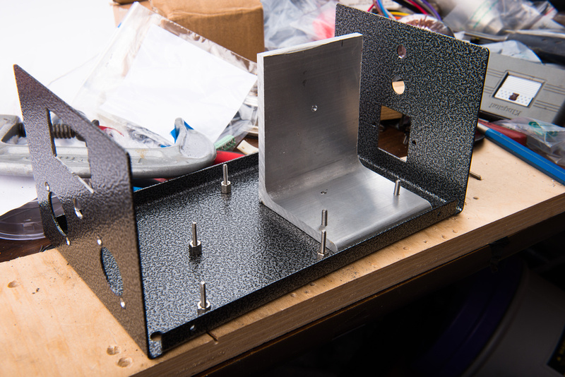
At this point, all of the metal hacking is done, and I can move on to assembly. If all goes well, Dan Deurloo will be able to make the final cases with pre-installed standoffs and pre-drilled holes so kit builders will essentially start from this point with everything directly bolting together.
I start by wiring up the mains. Since I am in the US, I wire the two 115V primaries in parallel. And, the secondaries should be wired in series for all builds to generate 230V.
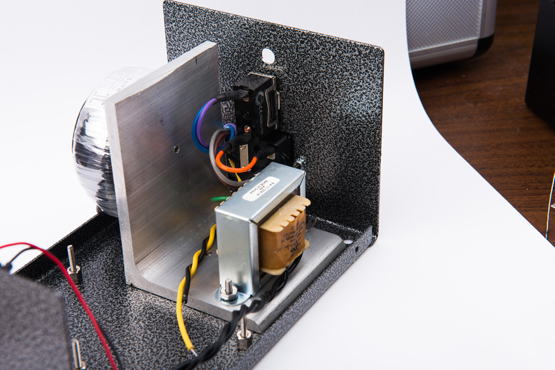
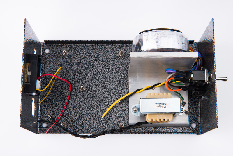
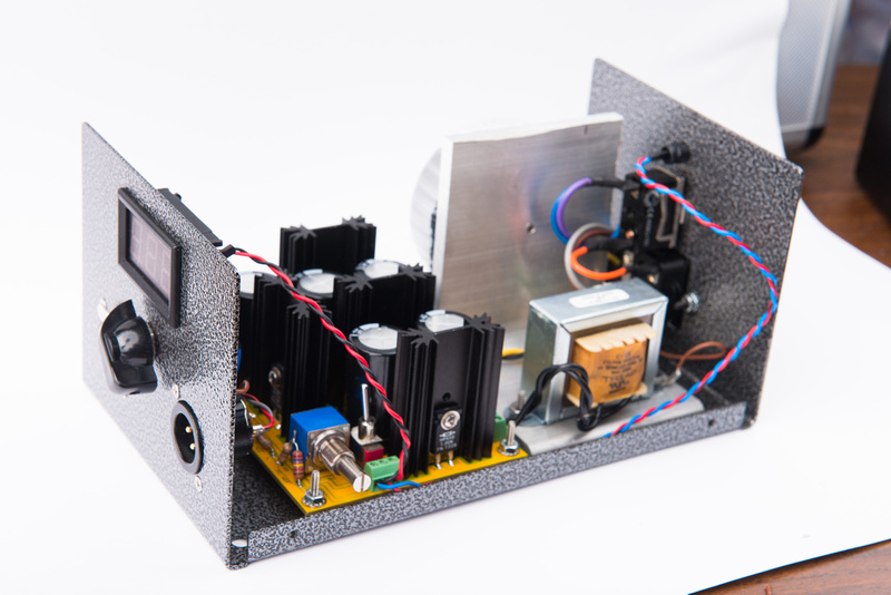
With a quick test-fit of the PCB, we can get a good picture of how the internal wiring will run in this layout. I feel it is pretty intuitive and the wire runs are straight forward. Matador has shifted the main screw terminal to the side of the board for easy access and he has put the test switch on the PCB as well to simplify the build further.
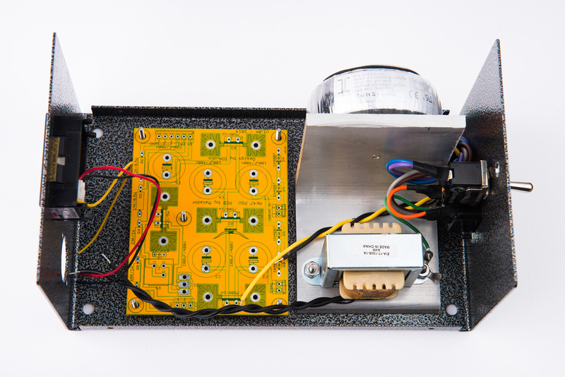
That's all for tonight. . . I feel like the rest should be downhill, and I am hoping to have this up and running quickly. I have no clue what I'm going to do with all of these mk47 PSU's I already have 3 built on this thread. . . this one will be a 4th, and I will at minimum have one more build to do for kit instruction documentation
My main purpose for this prototype build is to test function with the lower-cost, smaller, lighter, more readily available Triad 230V 25VA transformer that I had used on my 1st 2 builds on this thread. We will make sure the final case design fits the 200V Antec with the 6.3V taps because we do have plans to use the same case configuration and standoff locations to implement some of the other PSU designs for various microphones. I also want to nail down a final BOM for the 230V transformer since many of the values shift when the voltmeter is introduced into the passive PSU topology. These low-cost Chinese meters do not come with any documentation so it takes a little bit of experimentation to figure out the right resistor values.
I cut a 3" piece of aluminum L-bracket to mount my toroid and choke. Holes were drilled and tapped to install this L-bracket. I also cut a hole in the front face for a digital voltmeter as well as a 3/8" hole for the rotary pattern switch that I like to use. As I was merrily building, I remembered that Matador wanted detailed updates on the prototyping process because he usually does this stuff and doesn't have his workshop set up yet, so I brought out my camera and started properly documenting.
One of the most critical PCB positioning considerations is the attenuator pot which is now directly PCB mounted on the 3rd rev. board.

The end of the pot needs to sit nearly flush with the outside case so a screwdriver can be used to adjust B+ externally, but the screwdriver will not be able to enter the case by accident.

Some may find this method a bit crude, but I clamp and use the actual PCB as a drilling template so my standoff holes are exact. I know this board will fit with 100% certainty.

Once the holes are drilled and chamfered on the back side for flat head screws, I install my standoffs.


At this point, all of the metal hacking is done, and I can move on to assembly. If all goes well, Dan Deurloo will be able to make the final cases with pre-installed standoffs and pre-drilled holes so kit builders will essentially start from this point with everything directly bolting together.
I start by wiring up the mains. Since I am in the US, I wire the two 115V primaries in parallel. And, the secondaries should be wired in series for all builds to generate 230V.


With a quick test-fit of the PCB, we can get a good picture of how the internal wiring will run in this layout. I feel it is pretty intuitive and the wire runs are straight forward. Matador has shifted the main screw terminal to the side of the board for easy access and he has put the test switch on the PCB as well to simplify the build further.

That's all for tonight. . . I feel like the rest should be downhill, and I am hoping to have this up and running quickly. I have no clue what I'm going to do with all of these mk47 PSU's


