newbie builds ioaudio MK47 microphone

GroupDIY Audio Forum

Help Support GroupDIY Audio Forum:

This site may earn a commission from merchant affiliate links, including eBay, Amazon, and others.
We had a few problems to iron out with the PSU prototype.  Resistor values were shuffled around a bit to accommodate the voltmeter.  We also had noise in the microphone from the 2 wire LED voltmeter, so we made prototype adjustments to change over to a 3 wire setup and tap near the LED adding a filtering capacitor to suppress the voltmeter noise.  In actual use, it is really convenient to have external trim and voltmeter.  I guess given the wide operational tolerance of the system, you probably don't need to constantly fiddle to get "exactly" 105V, but it sure does feel good to know.

Moving to revision 3 of the PSU build. . . Matador has made numerous changes to the PCB.

- tweak overall dimensions for more heatsink spacing
- change to PCB-mounted pot for easier assembly
- move a few components around for easier future service (resistor removal after assembly)
- move terminals for easier wire-up
- add ground terminals

A lot of this stuff is streamlining so the build is more intuitive.  Revision 3 of the PCB will be printing soon and I believe that should be the final revision.  Dan Deurloo will then work on a custom case with the voltmeter hole pre-cut, standoffs placed, and toroid bracket made so everything will bolt together easily.  Sorry for the long lead times. . . we don't like to release anything half-baked.

The prototype as it sits now (with 3 wire voltmeter) will go into a capsule testing session in the studio and generally get flogged around a bit to confirm everything is running smoothly.  Next prototype will likely change from the Antek toroid which is quite a bit larger than necessary to the 30VA Triad 230V toroid for cost and simplicity.  We will design the case to accommodate the large 50VA Antek toroid in case we use the same footprint for other PSU designs that require the 6.3V heater secondaries, but if you can fit the Antek, you can fit anything really.
 
Hi Chunger/Matador

I'm in the process of putting together a PSU based on the Zayance PCB.

I'm planning on adding a few bells and whistles, one of which is an external voltage adjustment and LED Voltmeter.

I am using the Antek 230>200/6.3/6.3 transformer. I was thinking I could use the second 6.3v transformer output (the first is used on a jewel lamp) to power the voltmeter via a bridge rectifier and filter cap...? That way I don't have to mess with resistor values on the PSU board; I've already acquired all my chassis mount 10W resistors. Thoughts?

Do you think noise could be a problem in this configuration?

Will I need another filter cap across the voltmeter 'measure' + voltage line connected to my 105v out? If so, suggestions for a value?

I know you guys are working on something similar and so thought I'd ask here...hope that's ok.

Thanks in advance.


Today I finally had the chance to test my MK47 Mic and Chunger's point to point power supply. It's only been burning in for an hour now but WOW, it sounds fantastic! I followed Chunger's directions step by step and made only minor changes due to material availability (example: the Gnd bus wire I used is a larger gauge and was terribly difficult to bend, hence the tool marks on the G10 board).

IOAudio MK47/BeesNeez M7 Capsule/Western Electric 408A Tubes/GT-2B Body and Chunger's Point-To-Point Power Supply:
 

Attachments

  • IMG_1770.jpg
    IMG_1770.jpg
    124.9 KB · Views: 202
This build looks fantastic!  The heatsink configuration probably runs completely cool to the touch too  ;D .  I didn't think anyone else would emulate it because its a bit over-the-top.  Of all the projects i have attempted, the ptp power supply was one of the most educational and gratifying to complete.
 
The heatsink warms up ever so slightly, just enough to take the chill off!  ;D

I love building anything out of wood or metal and I have the "ultimate set of tools" in my garage workshop! Thank you for documenting and posting your build. Now that this is done I need a new project!  ;)

*here's a glamour shot of the power supply*


Attachments

  • IMG_1776_Fotor.jpg
    IMG_1776_Fotor.jpg
    500.8 KB · Views: 122
Just a little shout out !

certainly some of us who enter the DIY world, really don't know what we are doing;wing and a prayer and damn, I sure hope I am grounded, is kind of my approach !

I finished up my MKU-47 about a month ago, nice paper weight with no PSU but couple of days ago; dove into building the power supply

I just wanted to publicly recognize and thank people for being helpful, answering questions and leading me in the right gear directions:  of course, Max at ioadio, Chung and Matador, Cat5, Zayance and Dan at Collective cases, TonyC and the great people at Mouser !  I don't know what the hell it is about Texas women on the phone, long distance, but I want to marry everyone one of them :); those Mouser gals are great !

Pretty certain all parts are ordered; can't wait to fire up the gun !
 
chunger said:
p480731709-4.jpg

YES! OMG, yes!

chunger said:
A lot of this stuff is streamlining so the build is more intuitive.  Revision 3 of the PCB will be printing soon and I believe that should be the final revision.  Dan Deurloo will then work on a custom case with the voltmeter hole pre-cut, standoffs placed, and toroid bracket made so everything will bolt together easily.  Sorry for the long lead times. . . we don't like to release anything half-baked.

My MK-U47 is done and is now waiting on a PSU. =) Is a Binder connector option going to be available? Cannot WAIT for this full kit. =) Please keep us updated!
 
fazeka said:
YES! OMG, yes!


My MK-U47 is done and is now waiting on a PSU. =) Is a Binder connector option going to be available? Cannot WAIT for this full kit. =) Please keep us updated!

3rd revision PCB's have been received by Matador and he has shipped them to me for test build.
 
The cases come from Dan at collectivecase and you can order binder cut outs so as long as you have the binder connectors you should be fine ?!
 
hey chunger, i bought a u47 tube kit in your online shop incl. the psu, but the kind lady would not pass my package through customs because of the american power cable.  ::) They sent the package back and now i'd like you to simply remove the supply cable or replace it with a eu cable so it can finally pass customs. hope you understand! ;)

thanks
weiss
 
QUOTE: "I'm not sure if it is correct, but I tie my audio ground (pin 4) to my ground (pin 7) at the connector because I do not see a separate audio ground lead for the microphone.  Just the (B-) terminal."

Just a quick question. Regarding the grounding: Did you do a wire from XLR PIN7/PIN4 on the mic to B- on the PCB?

EDIT:

u47-1.JPG


I finished the mic with wire from mic pcb B- to pin4 (audio ground on PSU) BUT: I have this humming that seem to disappear when i do this (i dont tuch, just "encapsule" the capsule with my hand..):

u47-2.JPG


Any ideas?

/M
 
Ill just answer this myself for reference..
I just put on the body shell, and the hum went away.. :doh: ::) 
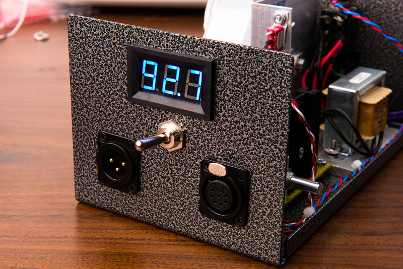
Also at first i got a relatively low volume and some white noise, but a change of tube sorted that out.. Im done!!! :) Pics:

MK47-1.jpg


MK47-2.jpg


MK47-3.jpg


My sirname is Brinch - so i made a custom badge (BB).. Also have for my U87 and C12.. :-D
 
mica said:
Ill just answer this myself for reference..
I just put on the body shell, and the hum went away.. :doh: ::)

Yup:  remember that you have a huge impedance hanging at the gate of the tube.  With 30M grid resistance, just a minuscule 33 nA of induced noise current will cause 1V of noise at the input to the tube, which will be happily amplified to 10's of volts by the system. :(

You must shield the entire system to prevent this, which is why solid grounding of the body shell and all parts is imperative.  Fortunately the wavelength of 50/60Hz hum is incredibly long (think thousands of miles), so even relatively large meshes (e.g. your fingers) are very effective at screening it out. 
 
Ill be taking a break now from doing mics, but man has it been fun! Thanks for all the help!

The family:

BBMics.jpg
 
chunger said:
fazeka said:
YES! OMG, yes!


My MK-U47 is done and is now waiting on a PSU. =) Is a Binder connector option going to be available? Cannot WAIT for this full kit. =) Please keep us updated!

3rd revision PCB's have been received by Matador and he has shipped them to me for test build.

Any word on these 3rd revision boards?  There are a bunch of us waiting with bated breath for this "best in show" U47 supply.  On fact, I have promised to build a few when they are available and the natives are becoming restless.  Thanks to you and Matador for helping to raise the bar on these projects.
 
The boards are in my hands and i am about 2/3 done cutting and prepping the case.  This prototype will use the lower cost triad 230V 25VA transformer which will likely be kitted.

Another board sample along with meter is heading over to dan so he can finalize the standoff locations and drill holes for the build.

Pics soon.  This is top priority for me currently.

Category 5 said:
chunger said:
fazeka said:
YES! OMG, yes!


My MK-U47 is done and is now waiting on a PSU. =) Is a Binder connector option going to be available? Cannot WAIT for this full kit. =) Please keep us updated!

3rd revision PCB's have been received by Matador and he has shipped them to me for test build.

Any word on these 3rd revision boards?  There are a bunch of us waiting with bated breath for this "best in show" U47 supply.  On fact, I have promised to build a few when they are available and the natives are becoming restless.  Thanks to you and Matador for helping to raise the bar on these projects.
 
Back
Top