- Joined
- Jul 15, 2009
- Messages
- 2,301
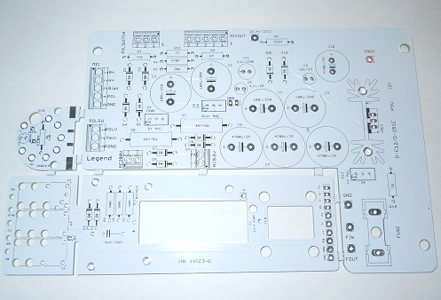
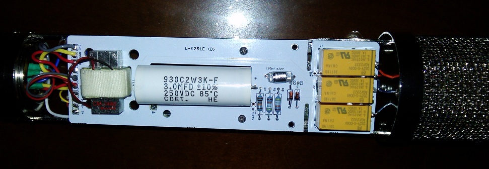
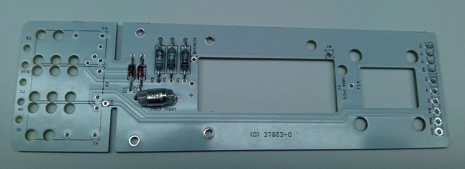
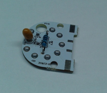
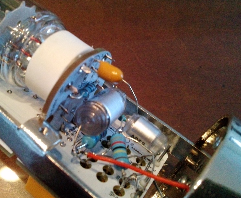
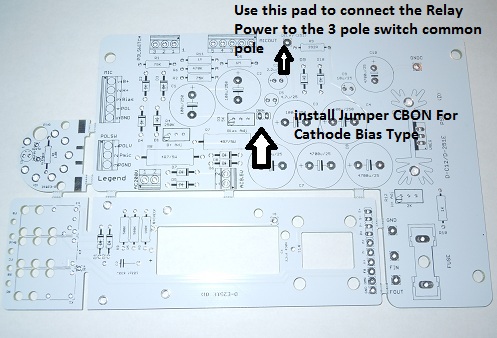
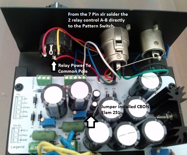
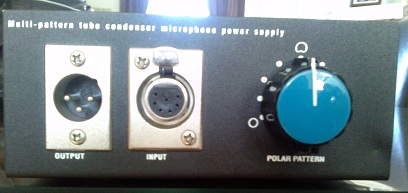
D-Elam 251E with True Pattern Switching on PSU ,
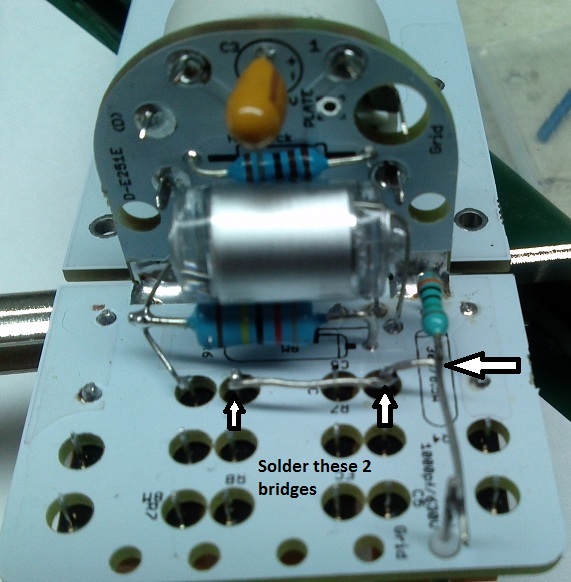
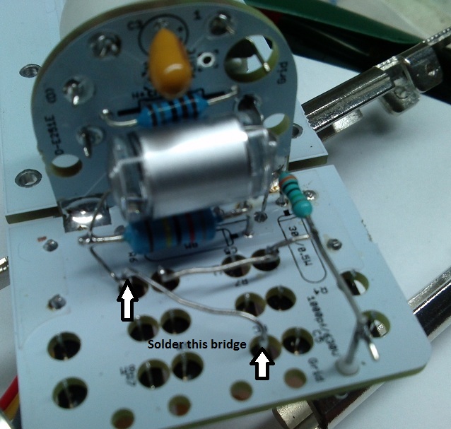
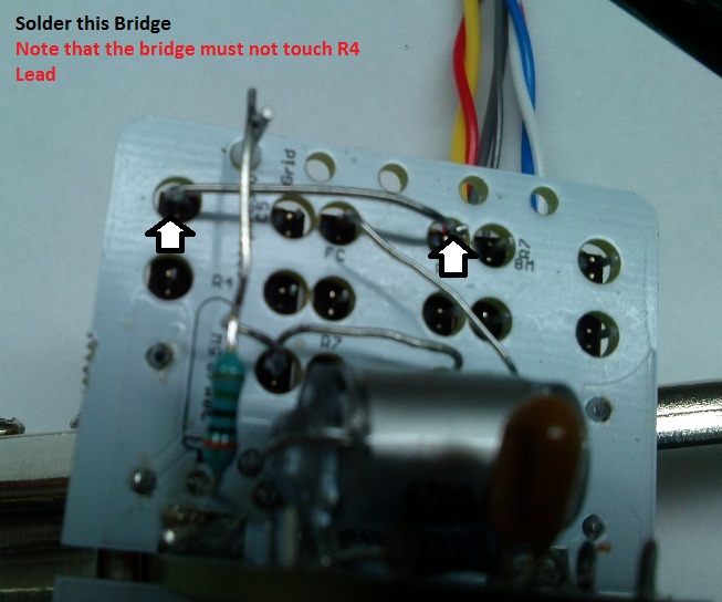
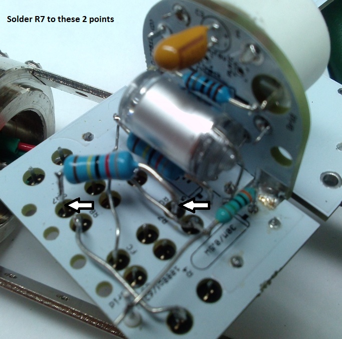
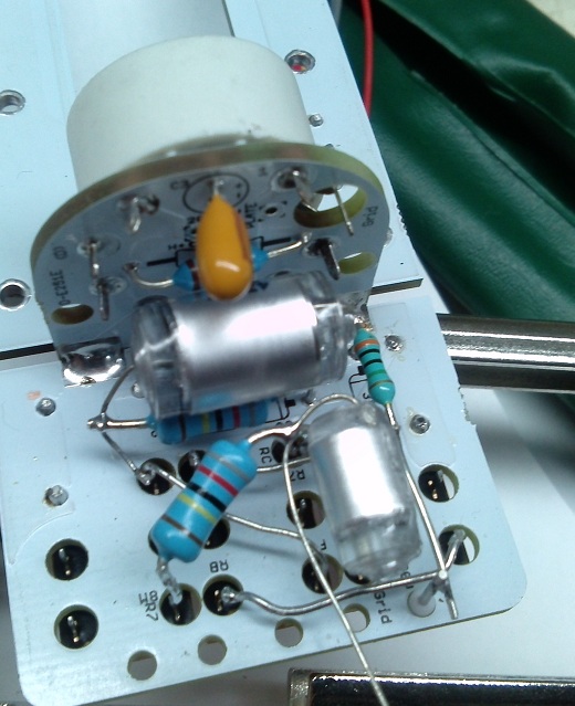
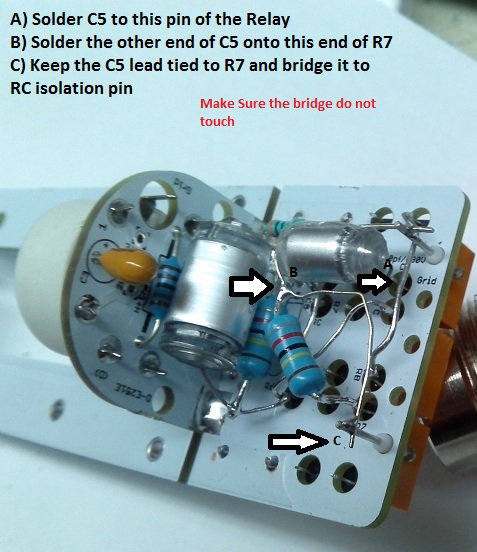
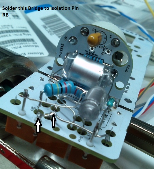
this was a very fun build. Specially the Point to Point HZ bridge, half PCb/half PTP for Optimal Results and Maximum Fun
Enjoy,
more Info soon at http://www.vintagemicrophonepcbkit.com Or http://groupdiy.com/index.php?topic=49675.0
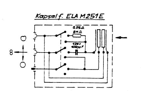
Schematic ELA M251E
https://cdn.groupbuilder.com/groupdiy/u/39511/58d1402a06402.pdf
Schematic D-E251E
https://cdn.groupbuilder.com/groupdiy/u/39511/58d1402a0643e.pdf
PsU
https://cdn.groupbuilder.com/groupdiy/u/39511/58d1402a06450.pdf
thanks to Trans4funks1 for this nice work.")
Microphone DiaGram
https://cdn.groupbuilder.com/groupdiy/u/39511/58d1402a06461.pdf
PSU DiaGram
https://cdn.groupbuilder.com/groupdiy/u/39511/58d1402a06473.pdf
PSU BOM Only
http://www.mouser.com/ProjectManager/ProjectDetail.aspx?AccessID=721fb79f74
Elam 251 BOM. (Missing From BOM 4700pf Polystyrene 630V and 1000pf Polystyrene /630V and 100pf Polystyrene 630V)
http://www.mouser.com/ProjectManager/ProjectDetail.aspx?AccessID=d2c3022a97
List Of interesting Tweaks From User and Group Member
I compile them as I go ,
Ok , here is some tweaks you can do from original schemtics,
SuggestedTweaks
100uF or more on the cathode bypass cap instead of 22uF (C3) bass response
increase the output LP filter by increasing the 120pF to 220pF or even 330pF ... (or more to taste) (C2) bass response
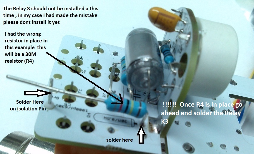
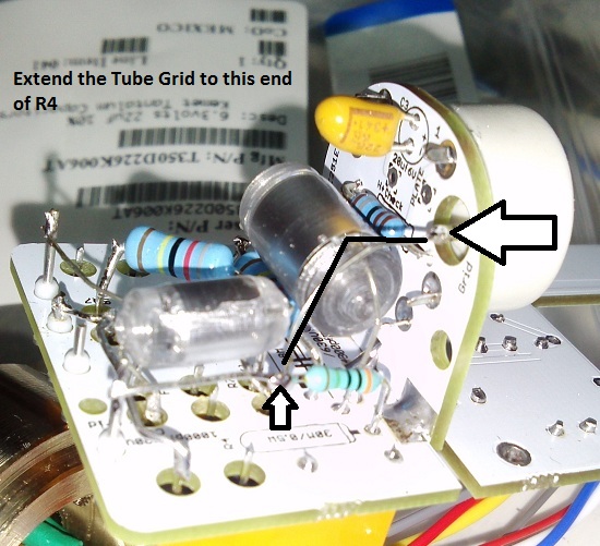
Grid to ground resistor higher 100m or 250m (R4) Bass Response
Increase or decrease output coupling cap to taste to modify low end response (C1) to taste


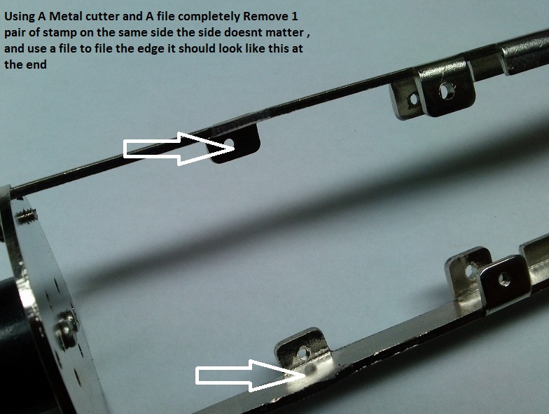
It is needed to get rid of a pair of high stamping Metal siders to proper with the aid of a metal cutter and a file


Best,
DAN,
this was a very fun build. Specially the Point to Point HZ bridge, half PCb/half PTP for Optimal Results and Maximum Fun
Enjoy,
more Info soon at http://www.vintagemicrophonepcbkit.com Or http://groupdiy.com/index.php?topic=49675.0
Schematic ELA M251E
https://cdn.groupbuilder.com/groupdiy/u/39511/58d1402a06402.pdf
Schematic D-E251E
https://cdn.groupbuilder.com/groupdiy/u/39511/58d1402a0643e.pdf
PsU
https://cdn.groupbuilder.com/groupdiy/u/39511/58d1402a06450.pdf
thanks to Trans4funks1 for this nice work.
Microphone DiaGram
https://cdn.groupbuilder.com/groupdiy/u/39511/58d1402a06461.pdf
PSU DiaGram
https://cdn.groupbuilder.com/groupdiy/u/39511/58d1402a06473.pdf
PSU BOM Only
http://www.mouser.com/ProjectManager/ProjectDetail.aspx?AccessID=721fb79f74
Elam 251 BOM. (Missing From BOM 4700pf Polystyrene 630V and 1000pf Polystyrene /630V and 100pf Polystyrene 630V)
http://www.mouser.com/ProjectManager/ProjectDetail.aspx?AccessID=d2c3022a97
List Of interesting Tweaks From User and Group Member
I compile them as I go ,
Ok , here is some tweaks you can do from original schemtics,
SuggestedTweaks
100uF or more on the cathode bypass cap instead of 22uF (C3) bass response
increase the output LP filter by increasing the 120pF to 220pF or even 330pF ... (or more to taste) (C2) bass response
Grid to ground resistor higher 100m or 250m (R4) Bass Response
Increase or decrease output coupling cap to taste to modify low end response (C1) to taste
It is needed to get rid of a pair of high stamping Metal siders to proper with the aid of a metal cutter and a file
Best,
DAN,