You are using an out of date browser. It may not display this or other websites correctly.
You should upgrade or use an alternative browser.
You should upgrade or use an alternative browser.
[BUILD] CAPI FC526~500 Series~FET Limiter Kit~Official Support Thread
- Thread starter jsteiger
- Start date


Help Support GroupDIY Audio Forum:
This site may earn a commission from merchant affiliate
links, including eBay, Amazon, and others.

'Chung has recently posted the last of the build pics. They can be found on the first page of this thread. He goes thru everything including initial startup tests.....but no calibration as of yet. Thanks 'Chung!! ")
NinjaFighter
New member
hey jeff,
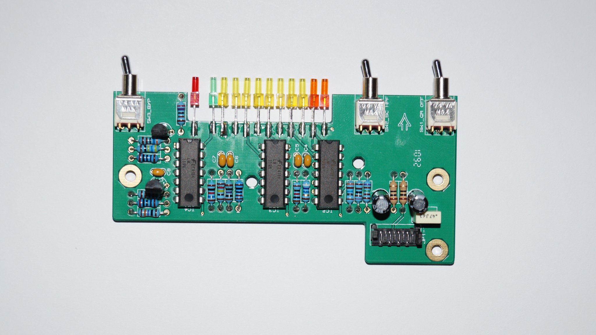
I seem to have a short somewhere in the meter pcb, I'm getting about 2.5 k on the +V and only 42 ohms on the -V. When i disconnected the meter ribbon cable from the main pcb i get around 2.5 k on the -V but the n the +V fluctuates like crazy from 100k and up.
Here are the pictures of the meter pcb. I've never put up pictures before so i hope they show up.
 DSC06293 by Jose Jimenez, on Flickr
 DSC06290 by Jose Jimenez, on Flickr
I seem to have a short somewhere in the meter pcb, I'm getting about 2.5 k on the +V and only 42 ohms on the -V. When i disconnected the meter ribbon cable from the main pcb i get around 2.5 k on the -V but the n the +V fluctuates like crazy from 100k and up.
Here are the pictures of the meter pcb. I've never put up pictures before so i hope they show up.
DSC06293 by Jose Jimenez, on Flickr
DSC06290 by Jose Jimenez, on FlickrJose, I am not really seeing anything jumping out at me.
Hello,
i just built my first FC526. I already built 2x VP312 et 2x VP28 (including both DOAs in each) and did not get too much in trouble.
Now testing my FC526 i'm getting 14.24V at TP10 so 14.24V goes up to the MTR's ICs.
- Why is this happening?
- Have i burnt the LEDs?
I'm getting -10.02 at TP9 and +16.35 / -16.17 at the edge connector.
Thanks for your help.
Martin
Attachments

I fixed a friend's build(s) here in town a few weeks ago. His main problem was that he intermixed 470R, 4k7, 47k and the 470k R's. They were randomly swapped around and it caused many different issues. I would recommend checking all of these as well as the other like R's. They will have to be verified with the color codes at this point since you can't accurately measure a resistor unless you desolder one lead.
drummingninja
Member
- Joined
- Jul 4, 2015
- Messages
- 8
Hey there, on mtr point 11 I'm getting 2.505v and 2.509v on two different builds. I see this is outside of the 2.498-2.502 range specified, is this problematic?
Also one of the two I'm building gives a fairly large volume boost on switching to ABI, but the other does not. Which is the normal behavior? Do you have any suggestions for what this may be?
Thanks so much for your time
Also one of the two I'm building gives a fairly large volume boost on switching to ABI, but the other does not. Which is the normal behavior? Do you have any suggestions for what this may be?
Thanks so much for your time
drummingninja
Member
- Joined
- Jul 4, 2015
- Messages
- 8
Dove deeper, got measurements from the audio path test that definitely deviate from numbers given:
with -30dbu (.024v) 1k test tone and fully CW RV2:
TP1 .012v
TP2 .212v
TP3 1.694v
Output 3.38v
Second unit has very similar readings. Litz transformer on these builds. One is 1731s, another is 2520s that are confirmed to work from a pair of LC53s. I do have -10v at TP9. The unit passes audio, sounds awesome and is functional other than issues with calibration. Using a true RMS meter. Thanks for the help
drummingninja
Member
- Joined
- Jul 4, 2015
- Messages
- 8
Just wrapped up two VP28s that turned out great! Still not sure what to do with the FC526, thanks to anyone with some insight.
noneother
New member
- Joined
- Jul 20, 2016
- Messages
- 1
Hey Jeff, I've recently completed my build of this compressor and had a few questions. I was getting voltages that were just barely out of the acceptable levels, so I bought a good quality multi meter (Fluke 87V) to replace the cheaper one I was using and got better/closer results, but I just wanted to run them past you to make sure everything is ok. I'm attaching your directions along with my actions/measurements for continuity.
**Pre-Flight Measurements**
1. With your DMM set to read resistance, clip your black probe to the GND lug. Now touch your red
probe to the “+V” DOA socket for each of the three discrete opamps. The resistance should be not
less than 500 Ω. Repeat for the “-V” sockets. Again, the resistance should be not less than 500 Ω.
Basically we are looking for direct shorts. Those are no good.
V+ at all three sockets were 2.592 K Ohms
V- at all three sockets were 641.8 R Ohms
Is it ok that the V- is that much lower than the V+
**Initial Power Up**
1. 1. The module needs to be flat in front of you on a bench or table and under power. A 500/51x
Extension Jig will be the easiest solution.
If you don’t have an Extension Jig already, here is a link to the subcategory at the store.
http://capi-gear.com/catalog/index.php?cPath=22_117_185
I'm using the Sound Skulptor Extension Jig for my tests. Verified to work correctly.
2. Apply power to the FC526 module. No opamps should be installed at this time.
Check
3. Set your DMM to DCV, clip your black probe to the GND lug. For each of the three discrete
opamps, check both the “+V” and “–V” socket with your red probe to verify approximately 16
volts.
V+ for all sockets was 15.33 V
V- for all sockets was -15.21 V
Is this too low? The rack I'm using is a fairly new Heritage Audio OST-4. On a previous build (Sound Skulptor Compressor) using the same rack in the same slot, I've seen V+ voltages be at 16.06 and V- voltages be at -15.96 so I'm fairly certain its not the power supply.
4. Measure DCV at TP9 to confirm between -9.98V and -10.02V. This is a critical measurement!
I get -10.02 but it will quickly jump back and forth to -10.03. Is this enough to throw everything off? I'm still new enough to DIY kits that I'm not sure.
5. Disconnect the module from the Extension Jig.
**Pre Calibration Information**
1. Before proceeding forward with any of the calibration steps below, make sure you have
between -9.98V DC and -10.02V DC at TP9. See the Test Points Guide for more info.
Done.
2. Before proceeding forward with the meter calibration steps below, make sure you have
between +2.498V DC and +2.502V DC at the “top” of the the meter resistor string for the
LM339 comparators, which is MTR point #11 in the pic. See the Test Points Guide for
more info.
Here I get 2.502 V, right at the edge of the tolerances.
My question is am I good to proceed with the calibration or is this indicative of a possible problem with the assembly?
Thank you!
drummingninja
Member
- Joined
- Jul 4, 2015
- Messages
- 8
Still haven't cracked the issues I was having above if anyone has any insight. Thanks!
IndietownRecording
Well-known member
- Joined
- Oct 14, 2012
- Messages
- 130
Has anyone calibrated these with their DAW? (PT11, Mac OSX) Or do I have to go buy a scope? Can someone recommend a plug to monitor the THD component of the output (Mac OSX)?
Blackdawg
Well-known member
Hey Jeff!
I am eyeing your 526 compressor kit.
Im curious about the Opamps. I definitely am going all discrete but am curious if mix and matching is recommended? Do certain ones sound better on the input vs the gain reduction stage and output? Or is it better to match all three?
I have heard the SLReddots and the gar2520s. To me the Gars are smoother and SLs are punchier. Haven't experienced the 1731s but have read they are more Neve sounding? How about the VF600s or 918s?
Any advice?
Thanks for all the work you do! Love your kits.
Was measuring some other stuff and realized I never measured these. I find the pair I have are fairly tightly matched for response, and unlike many comps, there are no response changes for any GR setting or SC filter setting, only level reduction measured. Those measurements were made with unity gain throughput knob positions close to the meter alignment setting positions, GR off, then checked with GR on.
bandwidth:
-0.5dB average of the two is 9Hz and 22kHz
-1dB average of the two is 6Hz and 32kHz
bandwidth:
-0.5dB average of the two is 9Hz and 22kHz
-1dB average of the two is 6Hz and 32kHz
New Soul Rebel
Well-known member
- Joined
- Mar 25, 2010
- Messages
- 135
Guys
Does anyone here have any experience calibrating an FC526 using a standard digital multimeter and Logic X ?
Its a pain in the ass trying to calibrate - logic meters are dBFS not dBU.
I know its possible as i've watched Hairball's vid. So looking to hear from anyone who has calibrated theirs this way.
Cheers Matt
New Soul Rebel
Well-known member
- Joined
- Mar 25, 2010
- Messages
- 135
Also - is it absolutely necessary to have a multimeter that measures AC at 1 khz.
It seems to me that a normal one is not accurate enough.
What's the best gear to do this job. Can you guys give me the lowdown. Cheers
Matt
It seems to me that a normal one is not accurate enough.
What's the best gear to do this job. Can you guys give me the lowdown. Cheers
Matt
New Soul Rebel
Well-known member
- Joined
- Mar 25, 2010
- Messages
- 135
Do I need a true RMS multimeter?
Similar threads
- Replies
- 4
- Views
- 688
- Replies
- 61
- Views
- 16K
- Replies
- 43
- Views
- 10K
- Replies
- 18
- Views
- 3K
- Replies
- 122
- Views
- 36K