500/51X Series SLQ51X SSL styled 4000 EQ / Filter

GroupDIY Audio Forum

Help Support GroupDIY Audio Forum:

This site may earn a commission from merchant affiliate links, including eBay, Amazon, and others.
Is it that you are hoping for the board to be laid out so that, for example, resistors follow a numeric order from left top to bottom right, or something similar to that? (That's a guess, but it's what I'm inferring from what you wrote; apologies if I've misunderstood). If so, that is very unlikely to happen, because the those numbers are referenced to the schematic. In other words, just because two numerically sequential components might appear next to each other on a schematic doesn't mean that they will be situated adjacent to one another on a circuit board, as there are numerous other complex factor at play in a pcb layout. The good thing is that the "slowdown" you experience as a result of hunting for component footprints gives you an opportunity to get familiar with the layout and develop a stronger understanding of where the various circuit blocks sit on the board.
What you are stating here actually -- IS -- possible to do, >> BUT!!! <<.....it is specifically dependent upon - which - PCB-design program you are using. Some of the more well-known "industry standard" and.....ahem.....more expensive PCB-design programs, have a feature which will -- re-annotate -- the PCB in a "numerical and logical" manner, exactly as "SadMonkeySound" desires. And, once the PCB layout has been "re-annotated", you then perform a "Back-Annotation" to the schematic, which then "re-annotates" the schematic and turns it from being an easy-to-read "numerically logical" schematic to a total -- nightmare -- where you might end up with R1 right next to R48 instead of R2!!! So.....> YES!! <.....it is possible to do this, but it may only be available to do so on the more higher-end PCB-programs and not the typical -- FREE -- software that is so commonly used within this forum.

"SadMonkeySound's" problems might also be due to a poor PCB components placement because a "good" PCB Designer would place their components closely following the original schematic and the schematic - should - have all of the component REF DES's grouped and placed relatively close to one another and in a somewhat "numerically-sequenced" order.

This concludes today's class on "Schematic & PCB Annotation Features In Modern CAD-Design Programs"!!!

/
 
Hello everyone. I built 2 SLQ51X black knobs last week. The builds went real smooth and they both powered up and passed audio with no problem. All controls control their respective bands and seem to sound correct. The problems start during calibration. I can get both units to calibrate just fine on high mid and low mid, but both units will not calibrate the high band and one will not calibrate the low band. Anyone have an idea where I should start my trouble shooting? Thanks in advance. Danny
bump
 
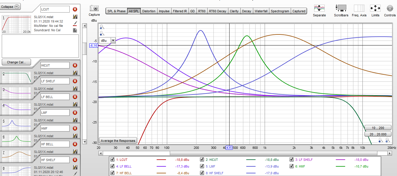
For All who love Measurments
iyzr2vgr.png

What did you use to make these measurements? I've had issues with REW and high end audio interfaces or ADCs, the interface itself is just interfering too much and I can't afford an AP device with the appropriate specs. A friend who works in audio and microphone design for years told me this will never work with an interface or ADC.

Just interested as this was what came to mind first, then I googled it and found out that DIYRE is actually doing exactly that as do other people but with varying results.
I use just RME interfaces nothing else anymore. I have different ones (UFX, Babyface Pro FS, Madiface XT, Directout Andiamo Converters)
 
What you are stating here actually -- IS -- possible to do, >> BUT!!! <<.....it is specifically dependent upon - which - PCB-design program you are using. Some of the more well-known "industry standard" and.....ahem.....more expensive PCB-design programs, have a feature which will -- re-annotate -- the PCB in a "numerical and logical" manner, exactly as "SadMonkeySound" desires. And, once the PCB layout has been "re-annotated", you then perform a "Back-Annotation" to the schematic, which then "re-annotates" the schematic and turns it from being an easy-to-read "numerically logical" schematic to a total -- nightmare -- where you might end up with R1 right next to R48 instead of R2!!! So.....> YES!! <.....it is possible to do this, but it may only be available to do so on the more higher-end PCB-programs and not the typical -- FREE -- software that is so commonly used within this forum.

"SadMonkeySound's" problems might also be due to a poor PCB components placement because a "good" PCB Designer would place their components closely following the original schematic and the schematic - should - have all of the component REF DES's grouped and placed relatively close to one another and in a somewhat "numerically-sequenced" order.

This concludes today's class on "Schematic & PCB Annotation Features In Modern CAD-Design Programs"!!!

/
I'll already work on this ;) I will arrange the components that it is more easy to find them ;) but I will not change the component numbers. Exactly because then schematic would read like a nightmare ;) I'll keep the component numbers but I will rearrange like I already did with PINK and ORANGE. More easy to follow ;)
 
Hi all, I am new here but have been reading the thread for a while, it was very helpful during my build and calibration! Thanks to Kevin for the awesome kit and everyone here who helps! I built the slq51x black RevB. I am wondering a couple of questions
- I notice an analog hiss that is quite a bit louder than other modules (i have tried other slots as well). Is this normal for this EQ? Or is there a component I can look to for this noise?
-There is about 10db drop when I engage the EQ, but in bypass it is fine. I see a similar issue earlier in the thread that mentions checking diodes and relais. How do I check if diodes are working and relais switching?

I built two of the original / old version SLQ51X units and I don't have these issues with either of mine. I would check your ICs, as well.
 
Hello, just got stucked while calibrating a black knobs rev. B. I could use some guidance as I still am a newbie.

LF and HMF are calibrated but LMF and HF boost and cut a wrong frequency range: with pink noise if I sweep the LF frequency knobs, the rta shows a sweep between 2 kHz and 20 kHz. For the HMF it's between 140 Hz and 2 kHz. I checked resistors, but might have missed the culprit.
Thanks in avance

ben
 
I've re checked all the resistors, caps and diodes and everything is in place and well oriented. The ICs and sockets are ok, variable resistors too. I still don't understand why th HF and LMF bands have their frequency range switched?
Everything works but that.
Any advice?

Thanks
 
Finally found that I had inverted C18 and C21 with C3 and C5 (Wima) capacitors. Everything is now working as intended. Finally learned to follow the schematics and pcb layout to learn from my mistakes.

I still have a problem to calibrated the LPF and the HPF as the 4 related trimmers don't do anything to the output level off the unit. Still show a -6 to -9 dB différence at the output when one if thé two filter is engaged.

Great sounding eq, thanks you
 
Hello!

I've completed building my SLQ51X Black Rev B kit, and have calibrated all bands except the low frequency band.

There is a strange issue where cutting lows does result in a cut (I've measured in REW), but no amount of knob turning can create any low frequency boost.

In fact, there is a low cut with the gain knob set at the zero detent. This does not change when I turn the calibration trim pot. Well... The amount of cut at the zero detent does change, but I am unable to get the zero detent to register flat in REW, and I am unable to register any low boost whatsoever by fiddling with the calibration trim pot and gain knob.

Turning the trim pot does have an effect when I've set the gain knob to cut lows rather than boost lows.

What the heck is going on here? I currently can't boost lows and I'm not sure how to troubleshoot. I've traced paths with a continuity tester to no avail. I'm hoping someone with deeper insight into the circuitry might have a hunch as to what's going on. Thank you!
Hello Alex,
Maybe check and solder again this LF gain pot. This happened to me once, one of the gain pot's leg was not soldered well and no gain could be added/removed.

Hope it helps,
Ben
 
I've spent a lot of time troubleshooting with no luck... I made a video to demonstrate my issue with the low frequency band if anyone has any insight. I feel like the behavior I'm seeing should point to some likely issues, I just don't have the knowledge to know what. Thank you!
 
With these type of EQs boost / cut is controlled by a linear pot and then two equal value resistors on either side. At center on the pot you should have equal value resistance to either side of the pot wiper. Attached is a generic schematic, R3 should equal R4, RV1 is a linear pot so each half should be equal at center.

Since you have a cut at center this suggest unequal resistance. Look for what might have caused this.

1) Is there a solder bridge somewhere in this area, perhaps on the pot?
2) Was a log pot used instead of a linear?
3) Are the resistors not equal? For example maybe two 2k were needed but instead 2k and 20k was used.
 

Attachments

  • Screenshot_20231019_095733_Opera.jpg
    Screenshot_20231019_095733_Opera.jpg
    43.1 KB
I have two brown knob rev.b EQs, and both sound incredibly nice.

- I bought one, liked it and later got the 2nd a while ago. Finally got around to building and calibrating as a pair. There is a tiny level difference when engaged and flat, between a 1-3dB drop in the 2nd one. I can work with it, but it does make me wonder what’s going on

The 2nd build also has a hiss, around -50dB in my DAW. Boosting highs makes it worse, subtracting highs -15 makes it more like the other one.

Also the 2nd one when engaged is reverse polarity? kinda weird, so I must have done something wrong. Visual parts look correct directions.

Otherwise they act the same. I can level match/ flip phase, they sound excellent. The hiss is a tad too much though. I swapped cards in the lunchbox, problems follow the card.

(Edit: I reconfirmed..
-polarity on the bad one flips when turned on, stays normal when bypassed.

-The hiss makes 10dB more noise when flat. All the EQs bands boost the noise, mostly notice the highs though.

-Signal, the bad one is between 1.6-1.9dB less output when playing music through.

-I reflowed some solder points, no luck so far.

Makes me wonder, would polarity be at the output IC? Input Relays? Could an opamp be to blame? Poor soldering of decoupling cap somewhere?

Great build and guide, I probably miffed a solder somewhere but I can’t tell yet. Visually they look identical except for C10,11 is smaller on the new one.. and the small upright nichicons near output are black on the new one, blue on old. I first one took me quite a long time and some mistakes. The 2nd was way easier to build so I’m surprised it’s giving the issues)
 
Last edited:
I have checked all above suggestions, still have the same issue. I verified every resistor in the circuit is correct one-by-one. I tried a different channel in my lunchbox. I am going to replace the LF gain pot, even though I had it out and verified it's working as expected. Anyone have any other ideas? I'm at a loss. I guess just continuity test every trace until I find something?
 
Last edited:
If you remove the pot does the response flatten out?

Also, on usual SSL eqs there is a trim pot on LMF and HMF but not on LF. So what is the trim pot that you were adjusting?
 
Last edited:
Back
Top