24 channel mixer the "Stereotype"

GroupDIY Audio Forum

Help Support GroupDIY Audio Forum:

This site may earn a commission from merchant affiliate links, including eBay, Amazon, and others.
Glad to hear they got there safe! I am always weary of shipping.
yeah, boards are all spoken for. I am toying with making this a white market stocked item, but will have to see about a few things.

don
 
Cool, I am glad to see there is interest. In the next few weeks I hope to have things sorted out for a new revision and a white market listing. i have some hopefully fun ideas for the next revision. They only add functions, but are all optional.

I'll keep you guys posted
don
 
Just *finally* wiring my 24 channel stereotype, and I have one more decision to make, and wanted to get input from those who've finished theirs.

My question has to do with wiring the stereotype boards' outputs to the ACA's ins.  Is there any reason why I shouldn't wire my three boards together "bus-style", then run a single feed from the "end" of the bus to the ACA, or should I instead wire each board to the ACA "star-style"?

In my case a single connection is simpler to fit (three of these boards plus an ACA/BO is a tight fit in rack-width), but don't want to do that if there is the likelihood of issues.  I can't see any issues myself, but it appears to me that both Don and Zayance wired theirs star-style, so I'm wondering if there's something I don't know...

Thanks!

Ryan
 
Actually I did mine using the "bus" method and zayance did his using the "star" method. You can see little jumps on my build if you look closely and know they are there. Either is fine, as far as I know. It's grounding you want to be a bit more particular with. I did that "star" style.


don
 
hakanai said:
Actually I did mine using the "bus" method and zayance did his using the "star" method. You can see little jumps on my build if you look closely and know they are there. Either is fine, as far as I know. It's grounding you want to be a bit more particular with. I did that "star" style.


don

Thanks Don -- That will save me some hassle.  It's pretty dang tight in the case, with lots of wires flying around.


OK.  I got my StereoType completed and powered up for the first time tonight.  The great news is that there are no big problems!  I'm pretty impressed.  That's a whole lot of solder connections for a relative newbie to get right, especially when you count 28 GAR2520s into the equation!

So it wouldn't be one of my projects if there wasn't at least one issue...  In this case, I've got one channel that isn't working right (1 out of 24 ain't bad!).  What it does: when I first turn the unit on, the channel seems to be working normally, but slowly fades out to nothing over the course of a few minutes.  I've ruled out the opamp by swapping a few around.  Regardless which amp is in the channel, it acts the same.

I checked all the upstream connections of course - no problems there.  So I've obviously got a problem in the signal path on the ST board, but I don't have any idea where to look first.  Don - any guidance you can offer?  I'm going to pull the board out and check everything over tomorrow, just wondering if the "fading out" thing sounds like any particular part of the circuit.

I promise I'll have pictures in the next day or two -- I've just been more interested in getting it running than I have in showing off.
 
I have not had this problem myself. what is the exact implementation you have built? Pans? Faders? DC blocking caps?
I was speaking with a friend last night and it seems like the DC blocking caps should be a recommended addition. He was saying large groups of DC coupled channels could start to interact with each other in bad ways. I don't know that this is what you are experiencing but if you didn't use the caps it could be a relatively easy place to start.

don
 
hakanai said:
I have not had this problem myself. what is the exact implementation you have built? Pans? Faders? DC blocking caps?
I was speaking with a friend last night and it seems like the DC blocking caps should be a recommended addition. He was saying large groups of DC coupled channels could start to interact with each other in bad ways. I don't know that this is what you are experiencing but if you didn't use the caps it could be a relatively easy place to start.

don

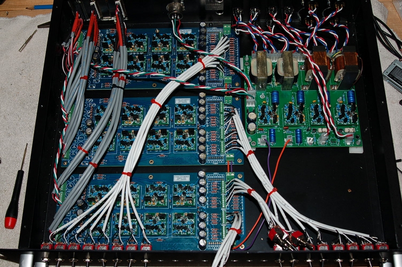
Ahhh -- Right, you don't know what's in my box...  It's three of your boards, so 24 channels.  I opted for no DC block caps, so those are jumpered over.  I also opted to not worry about the CMRR trim pots - those are jumpered too.  On the back end, I went with LCR switches using your suggested design, and those work really well.  No faders - I do all of my levels and actual pan in the computer.

The problem is weird - everything seems fine at power up, but one out of 24 channels slowly tapers off to no level.  I'm going to start by inspecting the signal path, looking for anything weird, but I'm concerned because the ST circuit is so simple -- I figured the problem would likely be in the opamp, since they're so much more complex...  But a quick swap from a working channel proved that to be not the case.  Also, when the channel "acts up", the pop from the pan switch is much louder than when it's working.

It's gonna be fun pulling all the cabling out with the board...  At least it's the board on the very end, and the way I put it together will allow me to pull the db25, and all 8 pan pots without disconnecting anything.

I will say that though that my cursory listening test on one song proved that this thing sounds worlds better than the Soundcraft board I've been using in this capacity.  Far more clarity and the guitars finally sound like they're where they should be in my mixes!

I'll report back once I see if there's just something simple going on.  Thanks for the response.
 
funkmuffin said:
...Also, when the channel "acts up", the pop from the pan switch is much louder than when it's working....
The pop is most likely DC offset for some reason. If all the other channels are working solid with the circuit as it, I would start by looking for a faulty solder joint in the problem channel. Just for kicks, and to tell you if you need these blocking caps or not, measure the offset on a good channel. Then measure it on the bad channel immediately after start up. Then measure it after the channel fades out. I would not leave it powered on long after this though, just to be safe. Might be a faulty solder joint on the shunt R at the opamp's input.
 
Well, I pulled the board with the offending channel, and reflowed all of the solder joints on channel 'E'.  put everything back together, and it's working!  I don't know what was wrong, but it appears to be fixed now...

Thanks for the help guys!

Here are some pictures:

guts.jpg

 
Sweet! Things are looking good in there. I'm glad to hear it was in fact a solder joint. Keep us posted as it enters regular mixing duties.

don
 
Back
Top