gswan
Well-known member
mac said:Can someone please explain what the "CP" stands for on my IC's and if it will be OK to use these TL071CP instead of TLO71?
C = commercial temperature range
P = plastic DIP package
A TL071CP is a TL071


mac said:Can someone please explain what the "CP" stands for on my IC's and if it will be OK to use these TL071CP instead of TLO71?
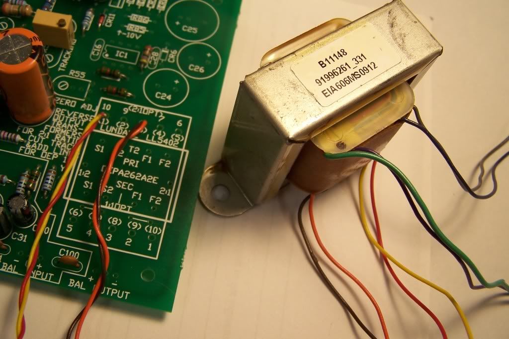
mac said:I am planning on going Ne5532 input and OEP output for starters, but might want to change to Lundahl input later. How involved is the change over? Is it as simple as just changing my inputs on the two boards and installing the Lundahl LL1540? Or is there some components that I would need to remove from the board to take the input section out of the circuit?
Hey Dan - I sent you the link of the Rev F thread so you could ask questions there - did you get it? This thread is for the G1176 which is very different visually so if you're looking for a drawing a G1176 one won't help you much...danjpiscina said:Hi Guys. I'm wiring mnats rev F with Hairball i/p and o/p transformers. is there an official wiring guide around here? lots of wires on the output one and it's kind of freaking me out! Don't want to get something wrong and fry the board! Thanks for listening.
DP.
gswan said:Pin 1 and 5 of the TL071 are the offset nulling pins. If you look at the TL071 circuit you can see that they connect across the 1080 ohm emitter resitors in the current mirror.
gswan said:Not sure what the NC pin is internally connected to. Sometimes nothing, sometimes the substrate. It could also be different between brands of op amp too.
I would not recommend connecting anything to this pin, you don't know what other effects you may be having on the op amp by connecting to it. It would be safer to simply add a small capacitor between pin 1 and GND to bypass the current mirror resistor (as an experiment). If this does the same thing then it's a more consistent approach.
mac said:Yes,
in essence this is my question, whilst the Rev "F" schematic shows the secondaries going straight to the output, for these boards do I need to return them?
Or is it just a case as you say of being "easier", in terms of hooking up. If i do wire the secondaries back to the board, should I remove R84?
Thanks,
Mac.
")


![Soldering Iron Kit, 120W LED Digital Advanced Solder Iron Soldering Gun kit, 110V Welding Tools, Smart Temperature Control [356℉-932℉], Extra 5pcs Tips, Auto Sleep, Temp Calibration, Orange](https://m.media-amazon.com/images/I/51sFKu9SdeL._SL500_.jpg)


