All things G1176 - the new "repost" thread.

GroupDIY Audio Forum

Help Support GroupDIY Audio Forum:

This site may earn a commission from merchant affiliate links, including eBay, Amazon, and others.
beaversaber said:
With the FET Q1 removed, gain staging appears to be more normal.  I get unity gain with both input and output knobs about midway

Have you actually performed any calibration yet?
The fet may be turned fully on, attenuating your signal until either Qbias is wound right out or you calibrate the unit. Bypass will not help you here.
 
beaversaber said:
I have attempted the calibration procedures, adjusting Qbias trim pot has no effect on the signal
Do you have the FET in the correct way around?
What is the range of DC output from the wiper of Qbias from one extreme to the other?
 
Yup, FET came with Hairball kit and is oriented the same way as MNATS pcb shows.

DC on the wiper of the Qbias pot varies from:

-.2 mV (fully CCW)
to
-2.446 V (fully CW)
 
OK, the Qbias range is correct.
Check the FET against a data sheet. The 2N5457 is oriented the opposite way from the BF245 device.
Wind the Qbias all the way to 0V (fully CCW) and measure Vgs. It should also be 0V. At this point your FET should be turned off unless you either have it reversed or it is dead.
 
the PCB is marked for the fairchild 2n5457, which is what I'm using.  I tried switching out the FET with Q10 and still had the same problem

Just to make sure I'm taking this measurement right,
I have the qbias fully CCW, negative probe of multimeter on GND, and positive on Gate of Q1?

This gives me .569V
 
beaversaber said:
the PCB is marked for the fairchild 2n5457, which is what I'm using.  I tried switching out the FET with Q10 and still had the same problem

Just to make sure I'm taking this measurement right,
I have the qbias fully CCW, negative probe of multimeter on GND, and positive on Gate of Q1?

This gives me .569V

That sounds about right. The FET should not be conducting in this case. If it is then it is probably dead. Double check the FET against the data sheet, not the PCB. Switching with Q10 won't help if you don't know whether Q10 is OK.

You can conduct gain stage testing with Q1 out. You should get about 26dB for the first stage and about 10dB for the second.

Did you check the DC bias conditions for all the transistors in the circuit?
 
Ah hah!

The FET WAS in backwards. Now getting signal with and without Q1 in.  Will try calibration procedures next and see what happens
 
Ok,
So while trying to do the calibration procedure for Qbias, I found that turning the Qbias trimmer has no effect on the output level.  I can turn it fully CW or CCW and see no change.  Any thoughts?
 
ok i'm back after doing some mistakes :p
so.

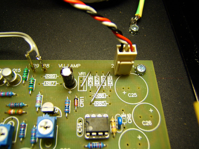
i have 2 1176J pcb where i put the components for the power supply. BUT (stupid enough) i use external little PSU so i must remove these components on the main board !

but i find nowhere the part list that you don't need if you use external powersupply. the only ting i have is this picture below where i can see the following parts removed :

R89/R87/VR1/CR9/CR7/CR10/CR8/R86/R85/C25/C26/CR6/C24/C16

then put the wire bettween CR8-R85 & VR1-CR9
is that all i need to remove ?
psu_wiring_main_board_jumper.jpg

 
beaversaber said:
Replaced the FETs with brand new ones, still no change in level when adjusting q bias

Then I'd suggest that you are performing the calibration incorrectly.
Did you test the gain of each stage first, to confirm operation of the amplifiers?
Did you test the DC bias conditions of each transistor in the circuit?
How are you doing the calibration?
 
dgoz...

ok i'm back after doing some mistakes :p
so.

i have 2 1176J pcb where i put the components for the power supply. BUT (stupid enough) i use external little PSU so i must remove these components on the main board !

but i find nowhere the part list that you don't need if you use external powersupply. the only ting i have is this picture below where i can see the following parts removed :

R89/R87/VR1/CR9/CR7/CR10/CR8/R86/R85/C25/C26/CR6/C24/C16

then put the wire bettween CR8-R85 & VR1-CR9
is that all i need to remove ?

Yes you're on the right track. If you take a moment to study the schematic and the pcb checkplot, you will see there is more than one way to achieve the connection of the two DC rails.
Also, have a look at mnats wiring guide http://mnats.net/1176-wiring.html
Mac


Attachments

  • PSU pcbs 002.jpg
    PSU pcbs 002.jpg
    41.8 KB
gswan said:
beaversaber said:
Replaced the FETs with brand new ones, still no change in level when adjusting q bias

Then I'd suggest that you are performing the calibration incorrectly.
Did you test the gain of each stage first, to confirm operation of the amplifiers?
Did you test the DC bias conditions of each transistor in the circuit?
How are you doing the calibration?

Here's my DC voltages for the transistors:
B         C         E
q2 1.038 1.727 0.556
q3 1.727 11.91 1.144
q4 11.91 29.71 11.32
q5 3.453 27.91 3.211
q6 16.28 27.91 28.46
q7 16.28 28.46 29.1
q8 29.71 16.29 15.69
q9 0.7         15         15.68
q10 13.66 12.9         12.9

q12 4.39         14.86 3.84
q13 14.86 29.72 14.24
q14 3.393 16.47 2.824
q15 16.46 29.72 15.9

I have not actually measured the output of each stage, but both input and output knobs seem to be working fine.  I will check this next.

When I try to calibrate, I send a tone out with the unit in bypass, output at about halfway, adjust the input knob so the tone is coming back at 0.
I then attempt to turn the qbias trimmer until I see a 1db drop in level, but nothing happens
 
Just going out to work.
Building another 1176 and i tried to calibrated and needle moves like it should.
I tried setting Q bias...vu lost 1db...so FET should be IN.
Now i can barely hear compression ...i barely hear it on the Slam mod.
I hear the Release working very nicely....attack is very subtle as well as ratios..
Only Slam mod works but very subtle compression...
Vu -meter shows  lots of DB's of compression but cant hear compression.

Any thoughts please.

Thanks.
 

Latest posts

Back
Top