All things G1176 - the new "repost" thread.

GroupDIY Audio Forum

Help Support GroupDIY Audio Forum:

This site may earn a commission from merchant affiliate links, including eBay, Amazon, and others.
I had a faulty voltage regulator. Tried to calibrate it and failed. Checking the voltages around the board, these are the values I'm getting.

        B        C          E
Q2 1.03 1.73 0.535
Q3 1.73 12.36 1.137
Q4 12.36 30.02 11.77
Q5 4.804 27.68 4.346
Q6 27.68 22.7 28.26
Q7 28.25 22.69 28.93
Q8 22.7 30 13.58
Q9 21.38 0 13.58
Q12 4.513 15 3.975
Q13 15 30 14.43
Q14 3.485 16.84 2.934
Q15 16.84 30 16.32
[tr][td]
 
Voltage on the collector of Q6 is too high. Vbe of Q8 and Q9 is way off.
Check R35, Q6, Q7, Q8, Q9. Maybe Q8 and Q9 are incorrectly oriented.
The rest of the DC states look OK in the GR amp and the input amplifier stages.

 
Hey, thanks for the reply. We immediately had a look at Q6 & Q7 (as the collector on Q7 is also off)

R35 is giving out the correct value.

If I had Q8 and Q9 wrongly oriented, is it possible that it would throw off Q6 and Q7? I've tried swapping round the position of Q6 and Q7 to see if Q6 was faulty, but it never changed anything and the values were very similar.

We're a bit stumped. I appreciate your response :)
 
Sorry, not quite following you there.

Are you saying R34 could be responsible for the problem? I'll take a look at that.

I've not got a close up of the area in question, but I shall get one.

I'll need to double check the orientation of the Q8/Q9
 
No, but being part of a feedback circuit, errors in later stages will effect earlier devices.
Q8 and Q9 would be my first check, since your Vbe readings are so far off. Make sure you have the correct devices in the correct holes and the correct way around. There are several traps with these ones.
 
Ok, having had another look, I'd definitely put Q8 in the wrong way round and I'm getting the right voltages. However, I'm still not able to calibrate my 1176.

When I set the output follow the guide, I can only turn the input up a tiny amount before the needle jumps all the way up into the red on the VU meter. I got the VU meter from Hairball. When I adjust the Q Bias trim pot, it does nothing.

Edit: When I set the unit to GR mode, the needle jumps hard right.

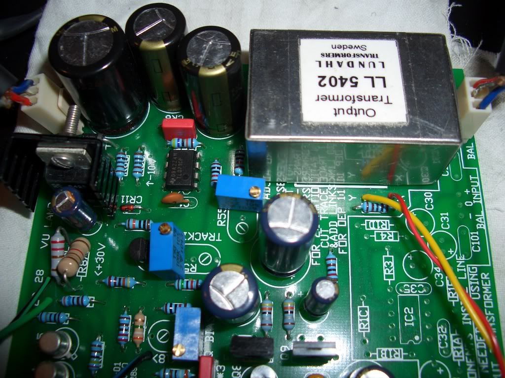
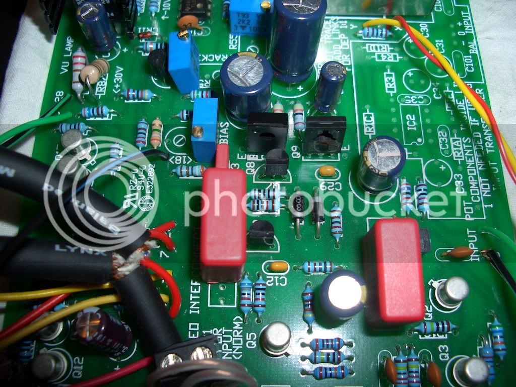
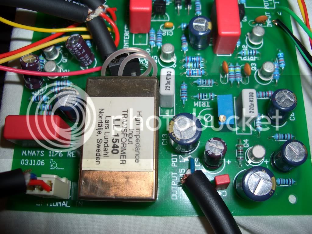
I've supplied pictures of my board. We've not tidied it up yet as we're still testing. I've followed the guides and double checked everything. It is passing a signal through. Again, thanks for any replies :)

1-3.jpg

2-1.jpg

3-1.jpg
 
Hi All,
      I'm sure this has been covered , but haven't been able to find what I'm looking for ... so here goes...

  I am doing a pair of Rev. J's , 

1.)  Do the BD135 /136  need to be matched , and if so what is that procedure

2.)  I read that it is a good idea to only populate the on board PSU and test voltages BEFORE populating the rest of the PCB ... well... I didnt read that untill AFTER I populated the PCBs - but I have / or was planning on using the M.nant  off board PSU with trimmers  .. SOooooo  ... is there a place to insert the (+) 0 (-)  from the off board PSU  OR do I just feed that into the on-boaed ( 24 - 0 - 24 )  ala GSSL  - OR do I now have an off board PSU for my next project  ;D

3.)  In a BOM I found for this project that I DIDNT use - it lists TAnt Caps in a few spots I already have Lytics  -  any problems with this ?  is one type in these positions better / worse ?

as always , thanks much for any and all help / advice ,

                                                                              Chip
 
audiophreak said:
1.)  Do the BD135 /136  need to be matched , and if so what is that procedure

No, these do not need to be matched.

audiophreak said:
2.)  I read that it is a good idea to only populate the on board PSU and test voltages BEFORE populating the rest of the PCB ... well... I didnt read that untill AFTER I populated the PCBs - but I have / or was planning on using the M.nant  off board PSU with trimmers  .. SOooooo  ... is there a place to insert the (+) 0 (-)  from the off board PSU  OR do I just feed that into the on-boaed ( 24 - 0 - 24 )  ala GSSL  - OR do I now have an off board PSU for my next project  ;D

Usually you would test the PSU before connecting it to the circuitry.
If you have not populated the PSU components on the main board then you need to use an external PSU module, and connect to the appropriate places for +30V and -10V

audiophreak said:
3.)   In a BOM I found for this project that I DIDNT use - it lists TAnt Caps in a few spots I already have Lytics  -  any problems with this ?   is one type in these positions better / worse ?

No problems with this.
Tantalum caps use a solid dielectric, which does not degrade over time so they are pretty stable. However they are quite delicate and often fail short circuit with only slight electrical abuse which can be catastrophic in some circuits. I've seen racks of computer equipment on fire after tantalum caps shorted the PSU rails.
Electrolytic construction is quite different and prone to eventual long term degradation (they dry out and ESR goes up). Provided you don't use a Wun Hung Lo brand, or get hit by the electro cap plague then you will not have any problems. In a properly designed circuit you will not detect any audible difference between a tantalum and a good quality electro.


Thanks so much gswan ,
     
  That clears up alot ... but still a little confused  on the PSU thing , unfortunately I had already populated the main PCB  including the on-board PSU , when I read about using the off board PSU for a dual unit.
  Is there a graphic or list of components to leave out ( or in my case remove ) from the on board components for the on-board PSU , such as the out lined area for the input stage / transformer option  " do not populate if using optional input transformer "  ?  .. and where do I connect / feed the off board PSU into the main PCB  ? 


  Thanks again ,
                    Chip
 
Have a look here. There's an image of the main board with components blocked out for the board without PSU (and using the LN input stage).
http://www.axtsystems.com/index.php?option=com_content&view=article&id=50:1176lnmodule&catid=34:1176ln&Itemid=62

I used a different external power supply to power the dual units, with a separate rail for lamps and leds etc.
http://www.axtsystems.com/index.php?option=com_content&view=article&id=84:psu8&catid=35:psu&Itemid=64

Geoff.
 
Thats what I was looking for   ;D

so I remove the greyed / blacked out on-board PSU components , install those four jumpers and hook up the off-board PSU as designated in that graphic  

 Thanks so Much  !!
 
I've been reading through this thread all day and I saw someone say that the wire going to 18 on the board should be closest to the wiper on the Q Bias pot, is this correct? I didn't think it made a difference?
 
well, i shall socket the damn oep's and see for myself !

watch out when you wire up the PSU that you either follow one or the other in regards to the wire jumpers on the rev j.
the polarities are opposite in Mnats vs. gswan pictures (4 jumpers/2 jumpers)

looks like theres a few dual rev js on the horizon then :)

what about the cs with *?
 
kepeb said:
watch out when you wire up the PSU that you either follow one or the other in regards to the wire jumpers on the rev j.
the polarities are opposite in Mnats vs. gswan pictures (4 jumpers/2 jumpers)

There are several ways to link out the on board PSU. Easy to trace out yourself and make sure you have the right supply rail going to the right location.

kepeb said:
:)
what about the cs with *?

Additional local PSU decoupling caps. A good idea to fit them.
 
Ok, I've managed to perform the Q Bias adjustment without problem.

When setting up the meter I'm having trouble.

I can zero the meter, but when I'm turning the attack back on, I can't raise the input level high enough to take it up to -10. Even all the way up doesn't take it up to the correct level. When I switch the attack off again, the level is back up at +3. I've seen that this takes a lot of back and forth, but it seems quite a bit off.

Any ideas?
 
Hello again  ;D

 
Transformer for 1176 50 VA too much ??
« Reply #6 on: April 03, 2006, 11:26:41 am
hi,
here's what mnats had to say about his dual mono G1176 build:
Quote
Found they were only drawing about 37.4mA each from the positive rail (no lights) so I put a smaller 30VA transformer in there to power both sides instead of the 50VA I had in there before.


so basically, if not using a lot of extra current draw due to meter lighting and such a 30VA PS transformer should work fine since each board is only drawing around 37.4mA.  That said, you should make sure that the PS transformer you get also has a high enough current rating for the total unit.
cheers,
grant

  I have this Amveco  62062 PT  -  25VA  -  1.04A  in series 24v  -  seems that even at  150mA to both comps would leave over 800mA  for meter LEDS  .. right ?
 

Latest posts

Back
Top