All things G1176 - the new "repost" thread.

GroupDIY Audio Forum

Help Support GroupDIY Audio Forum:

This site may earn a commission from merchant affiliate links, including eBay, Amazon, and others.
Yep, I've got 8.75 vdc across the output pot pads 15 and 16 (the other unit has nothing). A little bit of searching reveals that it appears I put C9 in backwards!!

Thanks so much for the help. This is really the first time I've ever had the chance to use a schematic to search these kinds of problems out, and it feels good to have figured it out.

Thanks again!
Sig
 
That would definitely cause a lot of scratching sounds!

You should check that C9 is still OK. If it's an electro they don't usually like being in backwards. Use an ESR meter to check it or junk it and put in a new one.
 
[quote author="syn"]have you connected your fets properly (pinout wise)? I've read somewhere around, that if you do that the wrong way , audio will still be passed, but no compression will occur...
[/quote]
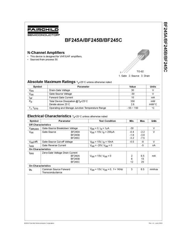
Here's the datasheet for the FETs I got. Looks like it's a direct match.
BF245A_Page_1.jpg
 
now that I think about it, my first mistake may be that I've been setting my meter to VU when doing the Qbias and not Bypass.... well, back to the shop in the morning.
thanks for the help so far.
Dan
 
I have noticed some things regarding the input and output pots that I just wanted to ask about. It appears that there is a very sensitive working level that seems to work best. Outside of this, the unit emits a strange kind of buzz/hum. For instance, when the output is set to about 12 o'clock - 2 o'clock, and the input is set to 2 o'clock - 3 o'clock, the unit is the quietest, and beyond that this hum and buzz occurs. Both of my units do it (although not at the exact same settings), so I'm almost simply assuming it is the nature of the circuit and just the way it is. Can anyone confirm this?

Thanks,
Sig
 
I can't confirm this, since both of my units are quiet over the entire travel of both pots.

Could be PSU or layout.
How much noise are you getting? Even at fully CCW positions?
 
Try moving your power transformer outside the box - If this helps, the hum comes from radiated transformer noise, and can be helped with appropiately shielded wireing and/or box space usage..

If you use the original Gyraf layout - i.e. not the mnats version - be sure to do the macic trace-cuts as mentioned several times earlier!

Jakob E.
 
Using the Mnats boards. There is zero noise with both input and output pots CCW, only in certain positions for each. All wiring is shielded with 2 conductor (and 1 shield) mogami wiring. I'll try the toroid thing, but it doesn't feel like that's the problem. The fact that both units do it makes me wonder.

Thanks,
Sig
 
[quote author="Siegfried Meier"]Yeah, I'm pretty sure that's normal. Neither of my 2 units show metering at all when in bypass.

Sig[/quote]
so... when calibrating the Qbias I assume that I have to use an external meter now? In the original manual it says to have the output cranked all the way up and then adjust input to what you need. On Gyraf's site its a bit more obscure...

[edit]
Ok... while going thru the GR meter tracking on Gyraf's site I see that no matter what I do, I have 5V at my output (measuring between ground and pin 1 of the xlr).
 
5Vrms? Probably picking up local mains noise (ie it's probably 50/60 Hz).

You should be measuring between pins 2 and 3 of the xlr (ie across the transformer output) since that's where the signal is.

I don't know the version you have constructed, however you should be able to use the meter as stated in the calibration procedure. Bypass mode simply shuts down the GR amp. Are you switching on bypass with the switch on the attack pot or have you put in another switch to do this?
 
[quote author="Siegfried Meier"]Yeah, I'm pretty sure that's normal. Neither of my 2 units show metering at all when in bypass.

Sig[/quote]

If you are metering GR and switch to bypass, you should see zero GR (ie meter at 0dB). Otherwise you should see signal activity if metering +4 or +8 from the outputs.
 
Well, I'm using the Mnats pushbutton boards, and I have an original looking front panel. The way the boards are laid out, it's GR on top, then +4, then bypass, then off. The front panel shows GR, +8, +4 and then off. So, at GR I see the meter resting at 0 dB, at my +8 position I see VU level out, at +4 it's bypass, and then off. A little backwards, but it's fine. I assume because I don't see level, at Bypass there is no level on the meter. Yes no?

Sig
 
[quote author="gswan"]
If you are metering GR and switch to bypass, you should see zero GR (ie meter at 0dB). [/quote]
If you mean 0dB and not 0VU, then you must use another meter for the Qbias or else the 1176 meter will just rest all the way to the left and just sit there... right?
I'm using Gyraf's 1176 boards over here.
 
No, I use the unit's meter to do Qbias calibration. However my switch arrangement is different, since I have the GR disable switch on my attack pot. Are you using the interlocking switch set for metering and GR disable?

Since GR disable just removes the signal to the GR amp, if you press this switch and also the GR metering switch together you should see the GR on the meter at 0 (0VU) since there is no GR. It should not change with signal input until the GR disable switch is released and signal now feeds into the GR amp.

For Qbias calibration, you need to start with the Qbias trimmer fully CCW, which should have the FET turned fully off. Now you need to monitor the signal using the +4 setting and the GR disabled. With the pushbutton switches is may be possible to press both the GR disable and the +4 together to do this. Now apply your 0dB 1KHz signal and perform the calibration.
 
Back
Top