All things G1176 - the new "repost" thread.

GroupDIY Audio Forum

Help Support GroupDIY Audio Forum:

This site may earn a commission from merchant affiliate links, including eBay, Amazon, and others.
[quote author="Siegfried Meier"]None of the shields are connected to both ends. I've very strictly followed Mnats wiring diagram instructions. 22 is shielded already, as shown in the wiring guide. I was inquiring about 20 and 21, which are just stranded and not shielded. I assume those are ok. What else to try?[/quote]

20 and 21 both carry a DC -ve offset voltage for the compression ratio. Does not really need to be shielded unless you are in a particularly noisy environment.
 
[quote author="Siegfried Meier"]Ok, did some more testing today. I was able to reduce some more hum by either connecting the Input XLR shield to the shield of the input pot, or to the shield of the output XLR - same amount of hum reduced in both instances. But, it's still not good enough - that weird P/S buzz still remains and drives me crazy. I'll keep picking away at it.

Sig[/quote]

Do you still get the buzz with nothing connected and all 3 pins of the input shorted together?
 
Didn't try that. I mean, I used them without any input connected, but I guess that's not quite the same thing. I've closed them and racked them now, but I need to pull them apart after I make sense of this FET matching thing, which I still have yet to make sense of. I'll check then. I'm pretty happy with the amount of noise there is now though - not perfect, but very very useable.

Thanks,
Sig
 
[quote author="gswan"]
- Enable GR (release the GR disable switch) and adjust the input control until -10 is indicated on the VU meter.[/quote]
the meter wont budge from 0Vu. just sits there.
There must be a wrong component in my meter section somewhere. What part on the schematic makes the meter rest at 0VU, and which section causes the meter to move when gain reduction happens? I would assume that this is the first place I need to look.
 
Sounds like the GR FET is not operating. It helps if these are matched, since they share the same Qbias. Does R55 allow you to perform meter zeroing?
 
[quote author="gswan"]Sounds like the GR FET is not operating. It helps if these are matched, since they share the same Qbias. Does R55 allow you to perform meter zeroing?[/quote]
I matched these FETs with the PRR rig and I just double checked them to be sure. I can zero the meter without an issue with the adjustment pot.
These FETs should be running pretty much the same voltage since they mirror each other, right? On Q1 I have 0V across the Gate Source and Drain. on Q10 I have 0V on the Gate, -8V at the source, and 12V on the Drain. These values are dependent on the tracking pot it seems.
I'm looking at the schematic and it seem that there is -10V from pin 4 of the TLo71 that goes thru R52 and then hits the source of Q10... so maybe that voltage is right?
 
[quote author="dustbro"]I matched these FETs with the PRR rig and I just double checked them to be sure. I can zero the meter without an issue with the adjustment pot.
These FETs should be running pretty much the same voltage since they mirror each other, right? On Q1 I have 0V across the Gate Source and Drain. on Q10 I have 0V on the Gate, -8V at the source, and 12V on the Drain. [/quote]

Something doesn't sound right here. The gates of both fets should have a bias voltage on them, putting them slightly into conduction. This is likely to be about -0.5 to -2V wrt GND. The drain and source of Q1 should be 0V with no input signal.

On Q10, the drain is at a +ve voltage less than 30V, depending on Id. The source will be lower, starting at around -9V depending on Id.

The 0V on the gate would mean that the fet is probably saturated.

[quote author="dustbro"]These values are dependent on the tracking pot it seems.
I'm looking at the schematic and it seem that there is -10V from pin 4 of the TLo71 that goes thru R52 and then hits the source of Q10... so maybe that voltage is right?[/quote]

The S and D voltages could be right, but the G voltage sounds wrong. See if you can trace out why the G voltage is not at the bias level. Start from the Qbias pot wiper onwards through the release pot to the FETs.
 
[quote author="gswan"]
The S and D voltages could be right, but the G voltage sounds wrong. See if you can trace out why the G voltage is not at the bias level. Start from the Qbias pot wiper onwards through the release pot to the FETs.[/quote]
There may have been a bad ground connection on the previous test. I just powered up the unit and let it sit for a bit and then traced the signal all the way thru to the FETs like you suggested. at the Qbias wiper all the way to point 7 I have 2.2V. that goes thru R7 and to Q1 where I now have a steady 1.59V. then thru R48 to Q10 where I have 1.81V.
I got a little excited and tried the calibration again... still no good. What's the next step to trace?
 
[quote author="dustbro"][quote author="gswan"]
- Enable GR (release the GR disable switch) and adjust the input control until -10 is indicated on the VU meter.[/quote]
the meter wont budge from 0Vu. just sits there.
There must be a wrong component in my meter section somewhere. What part on the schematic makes the meter rest at 0VU, and which section causes the meter to move when gain reduction happens? I would assume that this is the first place I need to look.[/quote]

Are you sure you are metering on +4 for this step? It should be reading your output signal directly (ie points X and Y).
 
due to my poor finances I try a cheap VU meter from an old pionner radio.
after the calibration I notice that only the 0 and -6 db read well , as example a 3db reduction is close of -5db and -12db is close to -7db.

there is any chance to make it work? or use a led based meter on this project?

cheers
Rafael
 
[quote author="gswan"]
Are you sure you are metering on +4 for this step? It should be reading your output signal directly (ie points X and Y).[/quote]
I'll check again... but I"m pretty sure I am. I'm sooo close!! crap
 
[quote author="12afael"]due to my poor finances I try a cheap VU meter from an old pionner radio.
after the calibration I notice that only the 0 and -6 db read well , as example a 3db reduction is close of -5db and -12db is close to -7db.

there is any chance to make it work? or use a led based meter on this project?

cheers
Rafael[/quote]

Did you check the meter against a known reference and level (external to the compressor)? This willl give you an idea of the meter's accuracy first.
 
I went to double check the voltages at my transistors (which seemed to be going well) and as I was checking Q8 the 4.3ohm resistors between Q8 and Q9 (R40 and R41) started smoking... Did one of those power transistors go bad and start passing too much voltage to those resistors? or is it coming from the other direction?
 
a solution to my problems! I went thru everything with a fine tooth comb. I had a 47k resistor where a 4.7k should go. Everything seems to be functioning great now!! (except on the unit that burnt up).
Thanks so much for all of the help along the way.
I'll do a proper test to make sure they are actually compressing some time tonight.
Dan
 
wow... I'm soooo much closer now. No matter what I do, there is a 6Db difference when I switch from bypass to GR or VU. even if the Qbias is cranked full CCW. Bypass is +6dB louder than when GR is engaged. Is the output transformer mod needed to match the gain between bypass and engaged? From what I read, it seems that this mod is only needed to match output to a real 1176 since there is no mention of this specific difference.
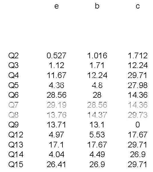
Here are some transistor voltages... something seems wrong with Q14 Q15.
1176VOLTAGES.jpg
 
Back
Top