All things G1176 - the new "repost" thread.

GroupDIY Audio Forum

Help Support GroupDIY Audio Forum:

This site may earn a commission from merchant affiliate links, including eBay, Amazon, and others.
Mike,
I used this in mine from Digikey TE62075-ND. Also you can try Avel Lindberg (www.avellindberg.com) you order direct from them and when I ordered my GSSL transformers there was a big price break just for ordering 2! Avel Lindburg seems to be a favorite around here.
Jon
 
[quote author="mischa"]
I do have to admit though that i had some difficulties regarding the 3 different q-bias adjustment instructions. The last i used was the on page one of this thread. To me it seems that the start-off point for this trimpot is in a way arbitrary, because the q-bias pot can be set to achieve a 1db reduction from any position, right? wrong, i'm afraid, but i don't know why.
[/quote]
Completely wrong. You must understand what you are doing before tweaking things. The FET needs to start off in a non-conducting state and then be biased just into conduction (a 1dB drop). Otherwise your FET is conducting all the time and needlessly attenuating the input signal (and operating at completely the wrong point in the FET characteristic curve)

So the Qbias start off point must be the position where Vgs is at the most -ve (ie wiper closest to R82).

[quote author="mischa"]
also, this one is the only one that should influence compression, right? So if i just turn it around without target, as soon as the compression sets in, the clicking also starts. :?

by the way, the clicking intensifies when i short the two left lugs of the attack pot.
[/quote]
You clearly have a fault in your GR amp circuit. Maybe you should also start tracing through this to find the problem? Are the DC bias conditions satisfactory? What are the bias point changes at different ratios? What is happening to your input signal at the drain of Q1 when this 'clicking' occurs?
 
ok, fets out im just trying to get signal through the amp sections. Ive checked dc voltages and they are inline. Q4e is at 11.7 but nothing comes out of it.

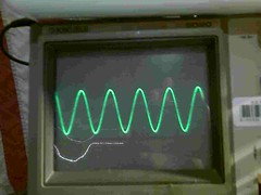
Input side of R6 - looks like this from the input jack through the opamp into R6 - nice pretty sine wave
2387511818_ccdce852d2_m.jpg


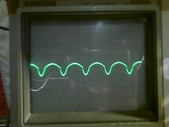
output of R6 - right before c5 things get wierd. R6 value is ok
2387513070_3025645cf2_m.jpg


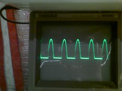
q3 collector

2386684971_43523056c8_m.jpg


anyone have some words of encouragement ?
 
I'd suggest checking the orientation of Q2. It looks stuffed. You may have other similar transistors inserted wrongly as well.

Here's a few scope shots for the input amplifier of a working unit to refer to (with compression disabled):

1. Q1 drain:
inputpot_top.gif


2. Base of Q2:
q2_b.gif


3. Base of Q3:
q3_b.gif


4. Base of Q4:
q4_b.gif


I've added more to my 1176 site which include the line amplifier and the GR amplifier sections.

Hope this helps,
Geoff
 
hi gswan,

problem solved. the two capacitors c3 and c4 had the wrong value, these were the only ones i missed to order and had to buy at a local dealer. i'll never buy there again ;)

regarding the calibration, your quote on page 1 of this thread was what i was looking for. only there it says how i have to adjust the bias pot BEFORE calibrating - fully ccw.

now it works & sounds alright!

thanks!
 
max, yes its post R6 pre c1. when i remove c1 it becomes a full sine wave again after R6 but i replaced it with a know good cap and same thing. im stuck
 
Then check Q2. It's either broken or it's inserted the wrong way around. The waveform distortion is highly non-linear, so it's not due to a faulty cap. Also check the orientation of the other transistors in the preamp section.
 
Just finished mine. If you want a power tranny go with Avel Lindberg Y236106

i had an issue with in and out pots. Fixed that. Now both pots are working. I get signal in and out. Used Mark's troubleshooting post to help. Followed it all the way to C15 on the - side. I can barely hear signal there. In other words I can perceive a signal but it is at VERY low level.

When I set the meter switch for +4 I get output metering. When I set it to GR I get a bit of deflection no matter what I set the ratio to. In other words it just sits at -20 and does nothing regardless of controls.

At this point since my test amp is battery powered and low quality I can't exactly perceive any compression. Thanks.

Ken-
 
[quote author="gswan"]
It may be useful for those constructing and having problems.
-Geoff[/quote]
Your site Is the 1176 information "Jewel in the crown" m8
Thanks to your site my dual worked "nearly" first time,
only let down by a couple of my own "Stupid" mistakes
:roll: :oops:
keep it up chap, The 1176 Needs You :wink:
:guinness: :thumb:
 
Thanks.
I'll keep it updated with anything else I can think of when people have problems getting it working.
Maybe there's a top-10 commonly-encountered problem list.
 
gswan, excellent site :thumb: Very helpful.

It is not immediately clear to me how I vary Vgs in the FET test fixture. I understand that Vds is the meter but what is Vgs?

Thanks

Ken
 
Thanks to everybody for all the great info - just finished a dual 1176 (Purusha case) w/Lundahl in/out on one and OEP in/out on the other. They sound fabulous - I'm wondering if anyone has a set-up like this because I'm getting less gain with the OEP's and the Ratio switch seems to be different, especially in higher ratios and slam mode - is that also your experience or should I check wiring. I checked other transformer threads but they all seem dead - no posts for over a year - and no-one seemed to have this issue. Thanks in advance for any advice. :thumb: :sam: BTW ... I'd post pictures but I don't know how and all those Purusha cases look the same anyway (albeit awesome)
 
gswan, my line-amp has a gain of approximately of +3,5 dB.
i use for Q8 and Q9 the BD135 and BD136 types.
in your part list you have BD139 and BD140 types and a gain of you line-amp is about +10dB.

for Q6 and Q7 i use the same as you BC560. also for Q5 (BC107).

is it the reason of more gain when you use the other BD types?
 
[quote author="kenrinc"]gswan, excellent site :thumb: Very helpful.

It is not immediately clear to me how I vary Vgs in the FET test fixture. I understand that Vds is the meter but what is Vgs?

Thanks

Ken[/quote]

Vgs is the gate-source voltage.
The source is connected to GND and you are using the trimmer to vary the voltage from 0V to -10V (or whatever -ve voltage you connect) on the Gate, relative to GND.
You need to measure both Vgs and Vds to plot the relationship.
 
Back
Top