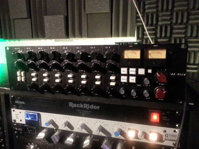
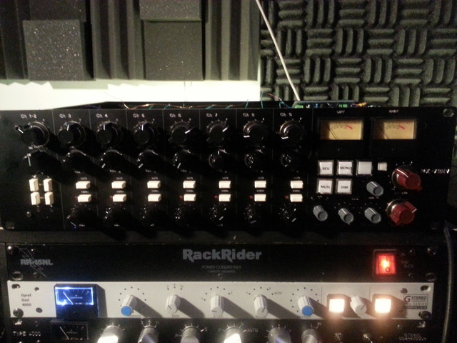
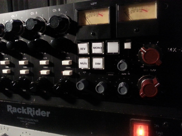
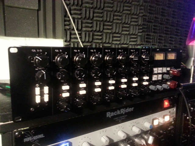
Another Neve 1272 summing mixer.

GroupDIY Audio Forum

Help Support GroupDIY Audio Forum:

This site may earn a commission from merchant affiliate links, including eBay, Amazon, and others.
Rocinante said:
Hense my confusion and how i came (wrongly) to the conclusion i did.

By convention, the primary is the winding on the left of the diagram i.e. brown/red and  white/black. To connect in series tie white and red together and connect to brown and black.

Cheers

Ian
 
I have spent too long searching my files for this document as it was what i originally used.  Reexamining it i see my errors. 

https://postimage.org/

So using the EA-10468 datasheet I believe according to this document it is in through orange (+) and purple (-) with gray and yellow tied together and out through Brown tied to white and red tied to black.  Correct? 
 
Okay so Mike from hairball just schooled me (bow's head in shame) and here's what I want.
Input is the sec in series
Input + = 7/Yellow
Input - =  10/Grey
8/9 or orange/violet tied together

Output is the primary in parallel
Output + = 2/3 Brown/White
Output - = 4/5 Red/Black

So yeah...

*I am gonna delete the other pics so if someone comes along they don't get bad information from my clumsy misunderstandings.
 
Rocinante said:
*I am gonna delete the other pics so if someone comes along they don't get bad information from my clumsy misunderstandings.

Glad you got it sorted out in your head at last. That is all that matters. I would leave the pics because I reckon there are plenty of others who have the same difficulty and seeing your successful journey will help them too.

Cheers

Ian
 
Ooops.    I had deleted those posts prior to seeing your comment.  I have actually followed the bad advice on a thread that didn't get corrected until pages later and it cost me.  I deserved it since i should have kept reading but I never want to do it to omeone else.

Onward.
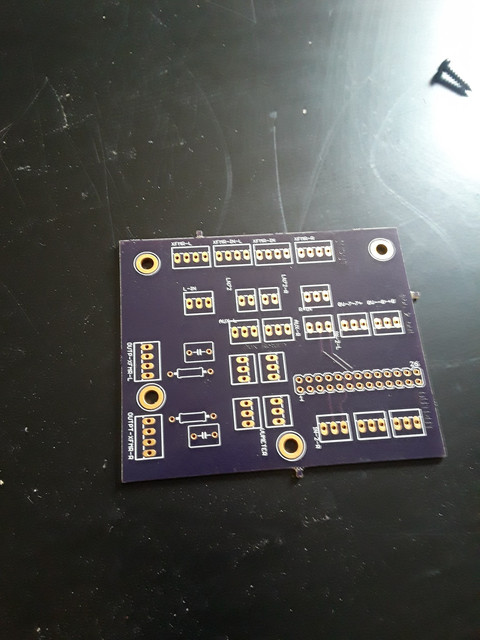
I have designed a small 'utility' board that acts like a junction for the master section, the aux return  and the Left and Right bus,  I am not sure about the o) and grounding.  Should I use a ground plane?  Should this be where I connect 0v to case or should I do it at the main out xlr's?  The Left and Right bus and 0v leave the backplane to this utility board and then onto the input xfmr and ln72 boards.  The EA-1166 doesn't have a ground and upon leaving the EZLN I have a shield out so I just ran a third wire from the 'Shield" out tightly around + and - to the utility board.  I think the rest of the board is self explanatory but I would love some feedback or suggestions.
https://postimage.org/

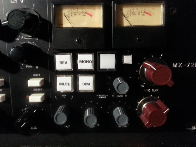
Also the master out header goes to a 'monitor controller' pcb.  Joe at JLM Audio has some great Passive Controller PCB's that I had read about on an old thread in the JLM forum.  I asked about it and would you believe it he actually had some he was getting to put up in the store.  The PCB is an easy way to create the passive controller project/tutorial by Rob Squire.  It is cheating and I am okay with that and it's awesome. 
Much cleaner than the wiring mess I had before.

 
Rocinante said:
Onward.
I have designed a small 'utility' board that acts like a junction for the master section, the aux return  and the Left and Right bus,  I am not sure about the o) and grounding.  Should I use a ground plane?  Should this be where I connect 0v to case or should I do it at the main out xlr's?  The Left and Right bus and 0v leave the backplane to this utility board and then onto the input xfmr and ln72 boards.  The EA-1166 doesn't have a ground and upon leaving the EZLN I have a shield out so I just ran a third wire from the 'Shield" out tightly around + and - to the utility board.  I think the rest of the board is self explanatory but I would love some feedback or suggestions.

As this is a passive board it is basically just wiring so you need to manage screens and 0V carefully. You definitely do not want a ground plane. I am sure you have read my grounding 101 document (if not it is in the power folder of the DIY tab of my web site) so you basically need to follow the rules in there. The key ones are:

1.  Cable screens should wherever possible but just screens and not carry signal. They carry interference currents safely away from the audio circuits. Easy to do for balanced connections, not so easy for unbalanced.
2.  The chassis (including screens), 0V and safety ground get connected at one point only.
3. For unbalanced signals where the screen is already connected to 0V, only connect it to 0V at the receiving end.

Cheers

Ian
 
Thanks for replying Ian.  I certainly have read your grounding 101 (printed and sitting on my scope for reference actually).
    I have removed the ground plane on the utility/distribution board but have kept the 0v.  Leaving the LN72 is +, -, and shield which get connected to the 1066 transformer and return to the utility board where the signal gets distributed.  The 1066 has no ground wire (but according to grounding 101 I would bypass one if it did) so should I connect the LN72 'shield' out directly to the output xlr?  Or should I run it to the 0v on the utility board? The later makes the most sense as I need an 0v for the master section control I believe. 
 
Rocinante said:
Thanks for replying Ian.  I certainly have read your grounding 101 (printed and sitting on my scope for reference actually).
    I have removed the ground plane on the utility/distribution board but have kept the 0v.  Leaving the LN72 is +, -, and shield which get connected to the 1066 transformer and return to the utility board where the signal gets distributed.  The 1066 has no ground wire (but according to grounding 101 I would bypass one if it did) so should I connect the LN72 'shield' out directly to the output xlr?  Or should I run it to the 0v on the utility board? The later makes the most sense as I need an 0v for the master section control I believe.

I am pleased you keep grounding 101 close by!!!!!!

The output of the LN72 is unbalanced. I cannot find a schematic for it so I am a little puzzled why it has +.- and shield. Actually I am not puzzled - I just remembered the output comes from the B+ and the 2N3055 connector so these will be the + and - and the shield will be connected to audio 0V. In which case leave the screen disconnected at the transformer end. On the transformer secondary you should again leave the screen unconnected at the transformer and connect it to pin 1 at the XLR ens of the cable.

DOes the utility board have power? If it does then take  its 0V back to the power supply with the power connection. If it has no power then it does not need a 0V.

Cheers

Ian
 
Thanks again Ian. I have removed the ground plane and 0v traces and am preparing the board for etching via press and peel. This will be my first at home self etch. I figured I cant justify getting it fabbed and its a simple layout which should be easier to self etch. Ive been wanting to diy my own pcb's for awhile and I just recently scored on a decent laser printer so no time like the present. i also have redrawn the b226 via Teekay's modifications as well as the 3415 which i am eager to also self etch.
 
Thanks guys. I failed at making my own pcbs  for the distribution PCB / utility PCB I'm just going to have it done it osh park or something and im currently awaiting some more loot for xfmrs. Currently it half passes audio. ;)
 
I'll post guts shots when its up and running for sure.  As far as the pcb's go i suppose i could have made the distribution circuit part of the back plane but the channels were from fourth  monkey and the neve line stage was from Martin, the insert are io pcb's from diy tubes and the monitor/master section is the passive controller pcb from jlm audio. Add some of Pier's app 992s and Jlm hybrids for doa's.  The aux send and returns will be jl regurgitators or neve 3415s. Im still tooling with that part.
And then a bunch of wiring.
Having everything separate gave me some flexibility. 

This distribution pcb was traced to work with the JLM passive controller.  It accommodates: in, xfmr in, monitor controller, vu meters, main out and monitor out.

 
Rocinante said:
I'll post guts shots when its up and running for sure.  As far as the pcb's go i suppose i could have made the distribution circuit part of the back plane but the channels were from fourth  monkey and the neve line stage was from Martin, the insert are io pcb's from diy tubes and the monitor/master section is the passive controller pcb from jlm audio. Add some of Pier's app 992s and Jlm hybrids for doa's.  The aux send and returns will be jl regurgitators or neve 3415s. Im still tooling with that part.
And then a bunch of wiring.
Having everything seperate gave me some flexibility.
I´m re-reading this thread again for inspiration and insight and I´m simply stunned by your work. And Ian is such a great contributor to this forum.

Do you have any hi-res pics of the front panel then?  8)
 
Back
Top