Behringer ADA8000 modifications..

GroupDIY Audio Forum

Help Support GroupDIY Audio Forum:

This site may earn a commission from merchant affiliate links, including eBay, Amazon, and others.
Personally, I'd strive for as clean a path to the A/D as possible....nice clean buffer in front, no diodes, no VCAs. I'd rather have a switchable input pad to deal with extra loud sources.

Cheers,

Kris
 
The problem is not high levels as I see it. If the level is high, you can just adjust the gain of the preamp. But what happens if someone drops a mic? Then the output of your input buffer would probably go up to 15V, and what would then happen if the ADC selfdestructs above 5.6V? Isn't that why input limiting is needed?

Best regards,

Mikkel C. Simonsen
 
and what would then happen if the ADC selfdestructs above 5.6V?

It probably won't.

The RME runs +/-17V and the Beh runs +/-15V supplies to the opamps driving the A/D chips - with no amplitude limitations whatsoever. If the chips were sensitive, the opamps would have been powered from +/-5V for sure.

Also, if keeping under Vs was chritical, it would surely have been mentioned in the specs.

Jakob E.
 
Here's a quote from a TI datasheet:
The analog input should not swing below analog ground or above the V CC power supply by more than 300mV. Schottky diodes may be used to clamp these pins to a safe input range, or the input buffer circuitry may be designed in a manner to ensure that the input swing does not exceed the absolute maximum ratings.

The same datasheet then includes an input buffer schematic running on +/-15V with no limiting at all... :roll:

Best regards,

Mikkel C. Simonsen
 
I see your point.

We may need to experiment with large input overloads to verify if the Wavefront chipset has the same weakness.

We are sourcing one of the 8000-boxes now, and will surely try is out as a heavy distortion box (under warranty) before beginning the mods..

:razz:

Jakob E.
 
Couldn't tell for sure what's inside those ICs of course, but
it's likely the inputs are internally rail-clamped for ESD-protection.

So signals would be clamped if they move some diodedrop past
the supply-rails of the IC.
 
[quote author="clintrubber"]Couldn't tell for sure what's inside those ICs of course, but it's likely the inputs are internally rail-clamped for ESD-protection.[/quote]
So only current limiting would be needed in that case I guess.

Best regards,

Mikkel C. SImonsen
 
I've never used anything like this because I dislike the idea..

I'm afraid there's little you can do to get rid of those (likely present) internal diodes. (OK, send me your open samples - we can laser them out for you :wink: )
 
What transformer would be suitabe for the input direct to the AD? Also, would be possible to use a transformer for the direct DA output?
I think would be great havig 2 of the channels with top trafos for using as "master channels" and the other channels with cheaper ones...
Any ideas?

Synthi
 
[quote author="synthi"]Also, would be possible to use a transformer for the direct DA output?[/quote]

No.

The D/A outputs seems to be rather high impedance, as well as in need of a 48KHz filter. See chip details at: http://www.profusionplc.com/static/images/data%20sheets/al1201.pdf

Jakob E.
 
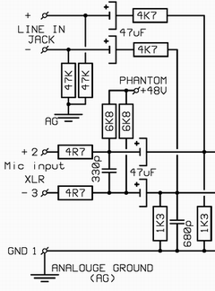
There are two resistors missing on Gyrafs ADA circuit that should be in series with the line in jack. As the the gain range is 10 to 60dB for Mic in and -10 to 40dB on line in suggesting a 20dB pad on the line input. So there should be 2 x 4.7K to 5.6k resistors in series like shown below.

Input%20correction.gif


Also some mod ideas in the PDF link below

-Mod input for transformer input mic pre by cutting tracks and adding 1:1 or 1:2 input transformer.
-Change opamps from TL074 to LM837 type which are low noise and can drive 600ohm loads.
-Convert line input to line output for zero latency monitoring and so mic pres can be used in ohter analog systems.
-22uF caps to Bi polar types.
-Remove output 220R resistors and wire 1:1 output transformer to the four solder pads.

http://www.jlmaudio.com/Analog Mod.pdf


Joe
 
> Here it is - for now only the analouge sections including the converters.

Great drawing, Jakob. Thanks.

As Joe says, it seems mighty likely that there are some series resistors on the line-in. As it stands, the gain is high and the input impedance is very low. Say what you like about B-co, they don't make inputs THAT odd.

The mike-amp bias looks wrong to me. Unless B-co is more clever than I am tonight, the 825R resistors (and diodes) must go to -15, not ground. (Or else the Bases are biased-up somewhat... I can't picture that just yet.)

With those corrections: it isn't sexy and it isn't best-possible performance, but I don't see where it sucks. The cascade transistors do give a pretty good mike-amp. They get the signal above the noise of the TLO74. The TL074 however does strain with that attenuation network hanging off its butt. A beefier amp might improve sound at the highest levels, or you could just not push it to the maximum.

I like Joe's suggested LM837. I'm not sure the noise matters, but the output is a lot beefier, and like 5534 they were designed to be audio-aware.

If you go Joe's full mod, losing the transistors, then a low-noise like LM837 is wanted.

> how would you limit the input signals to avoid killing the chip?

In this case, or any similar case, the 1K1 and 470 resistors pad-down the +/-13V swings to 2.3V swings at the ADC pins. No danger.

> drive the differential inputs on the converter directly with an input transformer - bypassing ALL the A/D analouge parts..

I did some calcs on a similar case, and I think to get the very-low impedance that the ADC pins need (to absorb their switching glitches) you wind up with a very low primary impedance. Something like 3K:100Ω Most gear will drive that, but.... And part of the idea IS to absorb switching spikes, which an audio transformer won't do well because of leakage inductance. So you might rather go 600Ω:20Ω with a good 20Ω resistor on the secondary, solid 600Ω impedance on the primary, which for some popular-price boxes (can you spell TL072?) is a Heavy Load.

Metering could be extended, but this simple thing tells you what you need to know: you are using 23 of the 24 bits (Clip) and you are using at least 17 bits (-40dB). On music, watching the "-40" light will tell if you are getting more than just 17 bits (light is mostly-on, you are using around 20 bits). I mean, golly, this thing claims 144dB dynamic range!!! I know this aint true, that the bottom bits are all noise and the top-bit may be TL074 strain, but that still leaves a big target. I thought 24-bit was supposed to FREE us from meter-slavery, why meter?

If you already have lovely mike-amps (or live at line level), and do NOT need gain control, then cut the wires from front to back board and put a couple 4K7 in front of the op-amp with two 3K9 resistors for a diff-input.
 
Thanks Joe and PRR,

You have some pretty good points here.

The line input attenuation is done by two 10K line-in series resistors and the 1K3's to ground.

And yes, you're off course right - the bottom end of the transistor pairs goes to -15, not to ground.

I updated the schematic at:

http://www.gyraf.dk/schematics/Behringer_ada8000_analouge.PDF

Thanks for looking!

Jakob E.
 
-Mod input for transformer input mic pre by cutting tracks and adding 1:1 or 1:2 input transformer.

-Change opamps from TL074 to LM837 type which are low noise and can drive 600ohm loads.

-Remove output 220R resistors and wire 1:1 output transformer to the four solder pads.

Joe

Hi Joe
-Can I use 1:3,15 mic input transformer? You suggest 1:1-1:2, in that reason
would gain be same like with transistors input stage.

-Does opamps SMD or standard?

-Also I have 1:1 Beyer Dynamic 1K:1K. Does it works?

Thanks
Duka
 
All opamps are SMD.

Mic input transformer probably won't tackle the high output levels of the DAC. Use line or output transformer for outputs.

If the Beyer will work with full output (some 10VAC) at full bandwidth (down to 20Hz) it could be used.

But you really need to experiment yourself..

Jakob E.
 
[quote author="gyraf"]All opamps are SMD.

Mic input transformer probably won't tackle the high output levels of the DAC. Use line or output transformer for outputs.

If the Beyer will work with full output (some 10VAC) at full bandwidth (down to 20Hz) it could be used.

But you really need to experiment yourself..

Jakob E.[/quote]

Thanks
 
Back
Top