perhaps using a conductive plastic pot instead of carbon? But theres a reason why that would happen to a carbon pot which I havent run into on either of mine.... hmmm
You are using an out of date browser. It may not display this or other websites correctly.
You should upgrade or use an alternative browser.
You should upgrade or use an alternative browser.
[BUILD] 1176LN Rev D DIY
- Thread starter mnats
- Start date


Help Support GroupDIY Audio Forum:
This site may earn a commission from merchant affiliate
links, including eBay, Amazon, and others.
Biasrocks
Well-known member
thesystem said:Hi guys, I'm wiring my 1176 right now and everything is going well. I'm about to wire the T attenuator to the input tx but I want to use an original UTC 012 which I bought on ebay. How do I connect the wires?? And is there also a nice way to mount the 012 to the chassis cause it doesn't fit the hairball pcb. thanks!
The Urei schematic for the 1176 shows how to hook it up. Schematics are near the back.
http://www.jblproservice.com/pdf/Vintage%20JBL-UREI%20Electronics/UREI-1176LNmanual.pdf
Try using a capacitor mounting ring for the O12.
Regards,
Mark
thesystem
Well-known member
Thanks Mark, a capacitor ring might work.
I'm not that good in reading a schematic so please tell me if this is correct:
- positive output of the T att goes to 1 on the 0-12
- negative output of the T att goes to 5 on the 0-12
- 6 on 0-12 goes to input on PCB
- 8 on 0-12 goes to earth on the PCB
or is it just the other way around? (positive to 5, 6 to earth etc)
Just a few questions that are bugging me:
- Do I still need to add two 620 ohm resistors on the bottom of the T att PCB or isn't this needed anymore?
- I can't figure out how to mount the pots to the chassis and the knobs to the pots.. :-\ sorry for this stupid question
Thanks guys
Biasrocks
Well-known member
thesystem said:Thanks Mark, a capacitor ring might work.
I'm not that good in reading a schematic so please tell me if this is correct:
- positive output of the T att goes to 1 on the 0-12
- negative output of the T att goes to 5 on the 0-12
- 6 on 0-12 goes to input on PCB
- 8 on 0-12 goes to earth on the PCB
That looks right.
- Do I still need to add two 620 ohm resistors on the bottom of the T att PCB or isn't this needed anymore?
Looks like those are for the T Att, R2, R3 in the schematic (obscured in the REV D schematic but visible in other REV's)
So I would say yes.
Regards,
Mark
thesystem
Well-known member
Could someone confirm that the resistors need to be soldered to the T att PCB/T att on the 1176 rev D version 2? Just want to make sure ")
And could someone else please tell me how to mount the attack and release pots to the chassis?
Final question: Can I safely use the fuse on the BOM from Mouser in a 230V country? (It's the 1/4 amp slow-blow fuse from Schurter, part number 34.3111)
Thanks
And could someone else please tell me how to mount the attack and release pots to the chassis?
Final question: Can I safely use the fuse on the BOM from Mouser in a 230V country? (It's the 1/4 amp slow-blow fuse from Schurter, part number 34.3111)
Thanks
I would think the amperage or draw for the unit wouldnt be different based on the voltage, but I could be wrong. The pots (switch / pot) just go thru the chassis and are held on with a nut. I dont have any resistors on my hairball kit T-attys and the units work great.


![Soldering Iron Kit, 120W LED Digital Advanced Solder Iron Soldering Gun kit, 110V Welding Tools, Smart Temperature Control [356℉-932℉], Extra 5pcs Tips, Auto Sleep, Temp Calibration, Orange](https://m.media-amazon.com/images/I/51sFKu9SdeL._SL500_.jpg)


college101
Well-known member
Just completed my board and re-installed it! Got the correct-09.94 on the negative rail and a +30.05 on the positive rail...
Connected it to my variac for the 24 hour burn in process..
I double checked all my votages again, after an hour of being "ON"....BINGO--looks like all systems go here!
Glad I re-did it over...careful soldering and wiring is the key...NO hum at all either!
Connected it to my variac for the 24 hour burn in process..
I double checked all my votages again, after an hour of being "ON"....BINGO--looks like all systems go here!
Glad I re-did it over...careful soldering and wiring is the key...NO hum at all either!
college101
Well-known member
COMPLETED!!! I got her working great!! Calibration was a breeze..finally got it all together!
a couple words of advice for new builders...
TAKE your time...I found the soldering in this project to be time consuming...but well worth it
A note on R44...I completely left the jumper bridge connector OFF the build till step 3 of the calibration procedures where you are required to insert it...
There are two items in the build that require heat sinks....one is the voltage regulator, and the other is the output FET( i believe, but I maybe way off here)- it needs a bigger heatsink...mine gets super hot, and even with the thermal paste, it could be cooler....
Thanks to everyone on here who has helped me in the past..I plan to help anyone I can...and if you want to message me, feel free to do so...
gemini86
Well-known member
Glad you got it working this time!
Biasrocks
Well-known member
college101 said:Thanks to everyone on here who has helped me in the past..I plan to help anyone I can...and if you want to message me, feel free to do so...
Good for you, feels good huh?
That's what this place is all about, pay it forward.
Regards,
Mark
college101
Well-known member
Yeah guys...its so rad...funny how I thought it was working the right way, and now I can actually see what it is supposed to do! Its sweet...I need to buy a bunch more now...
About to start an eqp1a build...
About to start an eqp1a build...
gemini86
Well-known member
Nothing like a victory to get you motivated again ...
And so the addiction begins........
sr1200 said:Gaaaaaahhh!!! found the prob! the wire going to pad 22 was reversed on the attack switch! DOH! works fine now....
hi !
I got the same problem... The sound is OK, and Good
but no Compression...What you mean by "reversed" on the attack switch ?
Hi,
I have a question about my futur RevD board.
In mouser 2N5457 are obsolete.
In stock there are only 2N5457_D26Z and 2N5457_D74Z.
I can see no difference between this part, and data sheet is the same.
Is this parts are good ?
I have a question about my futur RevD board.
In mouser 2N5457 are obsolete.
In stock there are only 2N5457_D26Z and 2N5457_D74Z.
I can see no difference between this part, and data sheet is the same.
Is this parts are good ?
acoustix said:Hi,
I have a question about my futur RevD board.
In mouser 2N5457 are obsolete.
In stock there are only 2N5457_D26Z and 2N5457_D74Z.
I can see no difference between this part, and data sheet is the same.
Is this parts are good ?
hi,
the 2N5457 come with the Hairball-Audio kit
thesystem
Well-known member
Got my 1176 working perfectly today! Sounds exactly the way I expect it to sound
Next I'm going to swap the input tx from hairball with an original 012 tx and see what the sound difference is..
After that.. It's time for some 8 channel API 312 goodness ;D
Next I'm going to swap the input tx from hairball with an original 012 tx and see what the sound difference is..
After that.. It's time for some 8 channel API 312 goodness ;D
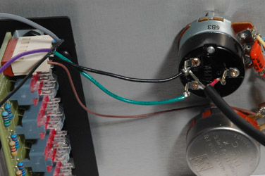
see the thick black wire thats connected to the back of the switch part of the attack pot? I had the lead (insulated wire) going to the pin on the left, and the shielding on the right (backwards) once I flipped that around.... "Aaaaaaaa"(angels singing)
BTW, the pic above is what it is SUPPOSED to look like.
sr1200 said:
see the thick black wire thats connected to the back of the switch part of the attack pot? I had the lead (insulated wire) going to the pin on the left, and the shielding on the right (backwards) once I flipped that around.... "Aaaaaaaa"(angels singing)
Here is mine :
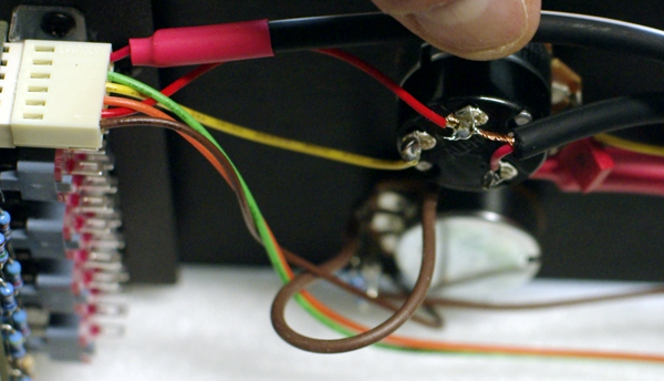
Am I good ?
note on the switch your black is my red (pin2), your green is my yellow (pin4)
Similar threads
- Replies
- 5
- Views
- 577
- Replies
- 2
- Views
- 559