Link?You must read about it.
You are using an out of date browser. It may not display this or other websites correctly.
You should upgrade or use an alternative browser.
You should upgrade or use an alternative browser.
Calcs for op amp loading vs THD?
- Thread starter atavacron
- Start date


Help Support GroupDIY Audio Forum:
This site may earn a commission from merchant affiliate
links, including eBay, Amazon, and others.
52V pp is 26.5V peak, which is 42.5mA into 600R, easily within the 85mA current limit.If the LME49724 can put out 52Vpp into 600R (86.7mA), and its short circuit current is 85mA
PP is as trap in this stuff as it means NOTHING at any given time, the thing is never outputting 52V, cannot output 52V and will not output 52V, worse for a standard differential line driver (Ignoring weird things that try to emulate transformer behaviour) each opamp is only required to hit one quarter of the pp output voltage, 52V PP is +-13V as the device driving each side of the line sees it.
As far as the load goes there are two ways to look at this, you can consider it to be 600R driven by the peak voltage across the line (26.5V) (not peak to peak voltage), or split the thing down the middle and consider one amp driving half the impedance to hald the peak voltage, you get the same answer either way.
Power dissipation might be an issue with these very extreme levels, but the saving grace is likely that they are not sustained, still need to look at SOA curves possibly.
I do not get the popularity of talking about peak to peak, it is not anything that ever has physical meaning except possibly when sizing bridge rectifiers.
PP is as trap in this stuff as it means NOTHING at any given time, the thing is never outputting 52V, cannot output 52V and will not output 52V,


Power dissipation might be an issue with these very extreme levels, but the saving grace is likely that they are not sustained, still need to look at SOA curves possibly.
So harkening back to my 3-amp OPA2210 + OPA210 FDA driving 440R when all is said and done into, say, a vintage 1176:
14Vrms aka 25.1dBu / .70707 = 19.8Vpk
19.8Vpk / 440R = 45mA differential
45mA / 2 = 22.5mA per side
45mA * 19.8Vpk = 891mW dissipation from the dual op amp
Correct? Or is it 45mA one side, 45mA other side, Class AB, ad infinitum?
What’s SOA?


Last edited:
What’s SOA?
Safe Operating Area
Nope, 19.8V pk looks sane, call it 20V, so each opamp is outputting +-10V at peak.
View attachment 107009
So harkening back to my 3-amp OPA2210 + OPA210 FDA driving 440R when all is said and done into, say, a vintage 1176:
14Vrms aka 25.1dBu / .70707 = 19.8Vpk
19.8Vpk / 440R = 45mA differential
45mA / 2 = 22.5mA per side
45mA * 19.8Vpk = 891mW dissipation from the dual op amp
Correct?
What’s SOA?
Current is 45mA and is being sourced by one opamp and sunk by the other, you do not get to divide this by two!
Now if you are driving into a resistive load (Not a given with old gear) then at peak and assuming a +-15V power rail, each opamp is dropping 5V (10V ouptut, 15V supply rail) at 45mA, so is dissipating 225mW *2 (There are two opamps), so 450mW.
However this may not be worst case as a lower output voltage may actually increase dissipation because the voltage dropped across the opamp output transistor will be increased (Try it with a 15V Pk output and see what you get!). The pathological case is driving an inductor where the current is 90 degrees out of phase and hence voltage across the opamp output transistor and current thru it hit maximum at the same time.
SOA stands for safe operating area, it is a graph with voltage on one axis and current on the other that describes the combinations that a transistor can survive (Note, voltage is voltage across the device, not anything else). They are notoriously published at unrealistically low temperatures (20c typically).
user 37518
Well-known member
Any particular reason as to why you used a Diamond Buffer? I've never found a sufficiently good reason to use it as opposed to more conventional configurations with the good old bias spreader.


Got it. I had edited the last post to ask just that while you were writing - and now D’s Kirchhoff reference makes sense. I also added the sourcing/sinking graphs and thermal info for this amp in case anyone has anything to glean from those. 45mA wouldn’t work at 125deg C but below 85deg C it looks plausible, given maybe a THD increase.Nope, 19.8V pk looks sane, call it 20V, so each opamp is outputting +-10V at peak.
Current is 45mA and is being sourced by one opamp and sunk by the other, you do not get to divide this by two!
Ohhhhhhhh. OK.Now if you are driving into a resistive load (Not a given with old gear) then at peak and assuming a +-15V power rail, each opamp is dropping 5V (10V ouptut, 15V supply rail) at 45mA, so is dissipating 225mW *2 (There are two opamps), so 450mW.
I will have to grok this.However this may not be worst case as a lower output voltage may actually increase dissipation because the voltage dropped across the opamp output transistor will be increased (Try it with a 15V Pk output and see what you get!). The pathological case is driving an inductor where the current is 90 degrees out of phase and hence voltage across the opamp output transistor and current thru it hit maximum at the same time.
I’ve been assuming 50deg C inside a well designed but tight and unventilated compact piece of gear.SOA stands for safe operating area, it is a graph with voltage on one axis and current on the other that describes the combinations that a transistor can survive (Note, voltage is voltage across the device, not anything else). They are notoriously published at unrealistically low temperatures (20c typically).
Last edited:
thor.zmt
Well-known member
Any particular reason as to why you used a Diamond Buffer? I've never found a sufficiently good reason to use it as opposed to more conventional configurations with the good old bias spreader.
I normally agree. The Diamond buffer is selected as we need a lot of drive for high levels into 600 Ohm.
That mean a simple EF will not cut it. I dislike EF2 (or EF3) plus Bias Spreader, thermal stability is problematic.
Diamond (instead of EF2) or Diamond fronted CFP (instead of EF3) are able to do a lot of heavy lifting at low HD and with correctly designed layout exceptional thermal stability.
I do have other options, but I like to keep some stuff for myself.
Thor
No. Each side provides 45mA. When one pushes, the other pulls14Vrms aka 25.1dBu / .70707 = 19.8Vpk
19.8Vpk / 440R = 45mA differential
45mA / 2 = 22.5mA per side
thor.zmt
Well-known member
Consider this line driver. It’s a +/-14dB differential trim, but I’ve simplified it here to just show minimum feedback current, ie a gain of 5.
View attachment 106938
Not sure what you are trying to achieve? Compatibility with a SE input? I think Birt is a better choice.
In the 600 ohm load scenario, ignoring cable length:
- U1 differentially drives 5K, 5K, 5K, 5K, and 678R. That’s ~440R.
U1A drives 5k // 5k // 334R or 295R.
Same for U1B.
- 39.6Vpp into 440R is ~90mA
Ok, that is ~14V RMS balanced and 7V RMS for U1A and U1B each.
So 7 / 295 = 24mA RMS or 34mA peak.
14V @ 24mA is 0.336W delivered into the various parts of the load (including the feedback network), with 0.295W ending up in the 600 Ohm load.
Each Op-Amp supplies 24mA RMS but with opposite polarity and thus the PSU current is appx 24mA on each rail.
The powersupply is +/-18V. The current drawn is thus 24mA RMS @ 36V or 0.864W. Of this 0.336W end up in resistors or load.
So roughly we dissipate ~ 0.53W with a maximum level sinewave in the Op-Amp and 0.04W in resistors.
Thor
I’m still interested in seeing the Birt forms we were discussing upthread, there are certainly applications, and would love to see whatever you’ve got on that. The additional loading of driving the inverter with the diff amp is a bit of a hurdle. Your note on what happens with its noise (turning into CM noise) was elucidating. The only issue with adding to CM noise on….well, any insert or output that shows up on a patchbay…is that you can’t necessarily rely on the receiver to have excellent CMR.Not sure what you are trying to achieve? Compatibility with a SE input? I think Birt is a better choice.
In turning a Birt into a differential line trim (y’know, with a single gain control across the center of the Rfs), I think it’s inevitable that resistor values would have to climb in order to get up into the sort of trim range that’s standard in a channel strip or EQ - at least 10dB if not 12-15dB.
As you say, one needs to keep some things for themself. So that’s why this example I’m using is simplified to the point of obscurity — it’s actually got buffering, CM rejection, and summing of multiple sources to the left, and multiloop gain control surrounding it, so the Rs values are lower than any other option I’ve worked out, and the 5K Rf is only applicable on one gain setting. And yes, the whole circuit (not drawn here obvs) does need to accept SE sources and perform acceptably as a SE driver if need be.
BUT the output aspects of this example are accurate for loading purposes, which is why I’m using it in this thread. I’ve got other SE-to-diff and diff-to-diff outputs that I need to optimize, all of which are fixed gain, and a nuanced understanding of loading is really crucial to be able to design those elegantly.
Last edited:
user 37518
Well-known member
Just noticed that you simulator claims around 0.000003% THD, and only 2nd harmonic, did you ever measure THD on the real deal? and, if so, how was it?I normally agree. The Diamond buffer is selected as we need a lot of drive for high levels into 600 Ohm.
That mean a simple EF will not cut it. I dislike EF2 (or EF3) plus Bias Spreader, thermal stability is problematic.
Diamond (instead of EF2) or Diamond fronted CFP (instead of EF3) are able to do a lot of heavy lifting at low HD and with correctly designed layout exceptional thermal stability.
I do have other options, but I like to keep some stuff for myself.
Thor
thor.zmt
Well-known member
Just noticed that you simulator claims around 0.000003% THD, and only 2nd harmonic,
Nope, it claims -134dB (-110dBV on +24dBV Signal) or 0.00002% H2. Now we are likely to see upper harmonics.
did you ever measure THD on the real deal? and, if so, how was it?
I have done so on other circuits, usually the match is quite close.
Thor
@Dan Mills in post #65 came to 450mW dissipation in U1 on dual 15V rails.
@thor.zmt in post #70 came to 530mW dissipation in U1 on dual 18V rails.
I forgot to specify that rails are in fact dual 15V, or maybe i did so too far upthread.
Translating Thor’s result to the correct rail voltage comes to about 442mW, which considering all the rounding we’re doing is basically the same result that Dan got, using a totally different method. Dan’s method has less steps fwiw.
Trying to replicate each method step by step on paper, I got caught up midway for different reasons - there are steps each of you skip because the interstitial math is intuitive, but that I get held up by. I’m very appreciative and will work on figuring out what I’m missing.
Last edited:
Note that that 450mW I got is an instantaneous power under the specific condition that occurs when the pair of opamps are pushing +-10V into the load resistor.
The power dissipation actually increases as you LOWER the signal amplitude peaking at 1/2 the supply voltage (so 7.5V) before falling again, and the pathological case is a square wave of 15V Pk differential. The REALLY pathological case would be to make the load phase angle 60 degrees or so (But that is just mean)....
Pretty much any of the pro line drivers will manage at least +24dBm into 600R and most will do +26dBm at least short term without melting given a suitable set of supply rails.
I have seen a D/A card (Drake?) done with a pair of TDA2030 driving a fairly large number of Lundhal transformers for the outputs, which I thought was a fun, if expensive approach.
user 37518
Well-known member
I forgot to multiply by a hundred to get it in percentage. Your plot says -90 for the 2nd harmonic and 20 for the fundamental, I am guessing those are decibels? There is also no other harmonic present that I can see, so the entire distortion is produced by that 2nd harmonic, that means the distortion is -110 dB, or 0.0003%
user 37518
Well-known member
I forgot to multiply by a hundred to get it in percentage. Your plot says -90 for the 2nd harmonic and 20 for the fundamental, I am guessing those are decibels? There is also no other harmonic present that I can see, so the entire distortion is produced by that 2nd harmonic, that means the distortion is -110 dB below the fundamental, or 0.0003%, which is not bad at all.Nope, it claims -134dB (-110dBV on +24dBV Signal) or 0.00002% H2. Now we are likely to see upper harmonics.
I have done so on other circuits, usually the match is quite close.
Thor
Last edited:
CJ
Well-known member
Peak to peak voltage is very important for vac tube power amps , caps should have ac and DC ratings but they do not do that anymore.
Also ac test points for say fender amps are usually in p to p values
Also ac test points for say fender amps are usually in p to p values
user 133392
Well-known member
- Joined
- Dec 13, 2022
- Messages
- 300
I've posted an article here on the many uses of the versatile Birt FDA: Visualizing the Birt Line Receiver As A Fully Differential Amplifier - Pro Audio Design Forum
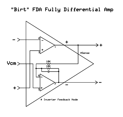
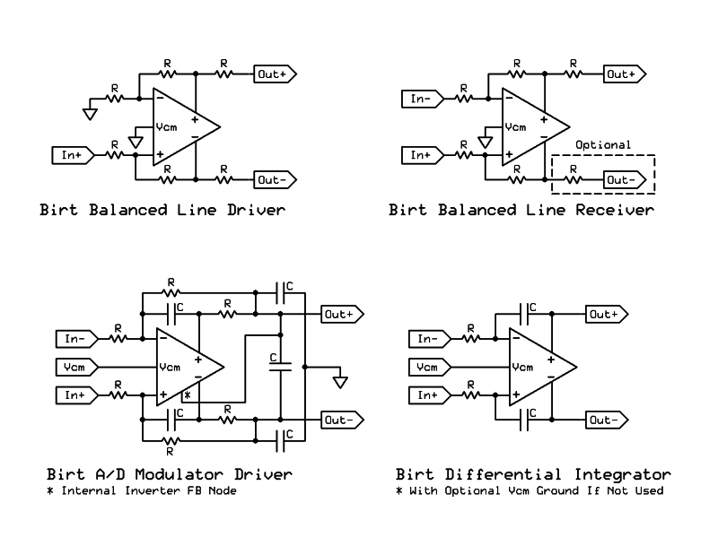
I've posted an article here on the many uses of the versatile Birt FDA
Nice one! Will read.
When do you use the Birt integrator vs your Deboo integrator? I’ve casually wondered how to work the Deboo in to applications where the amp being servo’d is not a CFIA…for example a mic pre whose heart is a coupla AD797s, or an OPA2211 (1612), or in less noise-conscious designs an ADA4625-2, or the new OPA2828, et al. I think the thing that always tripped me up is that the Deboo seems to rely on the supplies to establish its center point, so what you’re servo’ing to is actually Vmidsupply rather than the typical firm 0V/ground (?)….and your Birt form has a legit Vcm input that can simply be grounded.
Any pros and cons of the Birt receiver vs the double balanced input with 124X/128X parts you discussed on the forum and published that EDN article about? Your note about trimming the relative speeds of the input amp and feedback amp was key to my understanding of a variety of feedback systems.
Last edited:
So it’s good that i’m building a system around 15V dual instead of 18V dual. From a thermal perspective at the PCB (the supply being a different story!), it sounds like you wanna use the lowest rail you can get away with while keeping amps in their optimal headroom range. Using 7Vrms (19dBu) per side as a standard instead of 10Vrms (22dBu), in conjunction with amps that run reasonably close to RRIO under reasonably hefty loading, might open up the use of 12V dual for me. And that also explains the zillions of impedance balanced 5534 outputs in existence that run on 24V single.The power dissipation actually increases as you LOWER the signal amplitude peaking at 1/2 the supply voltage (so 7.5V) before falling again,
Now that’s a distribution amp!I have seen a D/A card (Drake?) done with a pair of TDA2030 driving a fairly large number of Lundhal transformers for the outputs, which I thought was a fun, if expensive approach.
Last edited:
Similar threads
- Replies
- 5
- Views
- 473