Calrec PQ 1061

GroupDIY Audio Forum

Help Support GroupDIY Audio Forum:

This site may earn a commission from merchant affiliate links, including eBay, Amazon, and others.
Ok I'm getting really excited, I'm a newB, but this a project is exactly what I've been wanting to do for a while, I'm so happy others are interested in the 1061 too. :grin:
 
you know, if you left off the filters (or just picked two freqs and used an on/off/on toggle), you could probably fit the EQ on a satellite board (a la gyraf style) and use lorlin switches for the freq select and bours 91 series pots for the cut/boost. I bet that would fit on a 19" chasis with enough room for the input attenuator, phase and phantom switches and a master fader. That would leave plenty of rooom on a small motherboard to mount the inductor and Id just put the opamps directly on the motherboard, no real need for plugin cards. Im just thinking about the cheap and easy. Keeping cost down and assembly easy would be cool on something like this, I would consider building a 6x2 box with something like this. If we are going to DIY this Id suggest off the bat that there is no good reason to keep the calrec form factor, lets all learn a lesson from the 1081 project and maybe lay this one out so its within reach of a few more folks maybe?

those are my intial suggestions thinking from the hip...

dave
 
the color coding for the input transformer is on the schem jakob is hosting.

yea, he told to do that.... but I didn´t get back in contact.

those are my intial suggestions thinking from the hip...

good ones btw... like Chris did with 1073:

http://www.wagrecords.net/neve2.htm

:guinness:
Fabio
 
Hey Dave,

those were my thoughts initially, much more interested in this than the 1081 and without all of the iron and complex switches - it should be cheaper too.

I agree that the whole thing could be put on one big board. I'm not too worried about the HPF to be honest.

As far as I can see the only real issue is the inductor. My initial thoughts were if one of the Sowter Neve replacements would work? I know that Neve, Audix and Calrec were all building very similar stuff around that time and there may be a chance it would work.

I mailed Brian Sowter again and he has the colour lead info for the TX now and I asked for possible pricing plus any more info about the inductor.

So we'll see how much that will cost.

Any ideas what he output iron is - its not illustrated on the schem?

If we could measure that inductor we'd be good to go I expect.

Cheers Tom
 
Actually I bet an email to brent averill would clear up his addition of the output iron and maybe he knows the where abouts of the MF inductor too?

Cheers Tom
 
I'll have some time today to get inside the 1061 a bit more. Are there any details that would be useful to the project that I could look for?

Brian
 
[quote author="BuzAllen"]I'll have some time today to get inside the 1061 a bit more. Are there any details that would be useful to the project that I could look for?

Brian[/quote]

remove the main board, scan both sides at high resolution, post, and let´s start the reverse-E :green:
 
I think this would be a much better utility project than the 1081. You could make this very expensive, but for sake of getting it done, Id put in my vote for a board set that is similar to the other gyraf calrec EQ. Its probably easy to assume that if calrec used a sowter input transformer, maybe they used a sowter output transformer, personally I could care what they used, Id build mine with all sowter iron. This really is another thing that is soo much easier for those of us in america, prodigy pro can import all the iron for us, assuming that many of us will be building this, I bet prodigy would be happy to stock the item for us if there is realistic demand beyond a few of us. this would make things soooo much easier than the 1081 thing. This would be a great great utility discrete transistor EQ project for the lab, we dont really have one of those yet.

dave
 
I've got a Calrec line amp (BL1179) from that era and the Sowters in it are 3777 input and 3955 output.

cal.jpg
 
Ive been looking at the schematic assuming we are having a "down and dirty" discussion about this as a group project, I dont see a good reason to stay with the original style input transformer or the attenuator switch. If sowter can do a transformer with 150/600 primary taps, you can use a dpdt on the front panel and maybe just add a pad to the mic circuit. This obviously changes the functionality of the box out of the gate, but also saves buying an expensive switch.

Just throwing some thoughts in the pot.

dave
 
I would pull all that crap from the input and do it as a 150/600 selector.

Also I don´t see whay one couldn´t use a 2pole 2 position switch for the gain control. Less steps, but I don´t care. There is a fine gain control in there already... This would be much cheaper.
 
I agree. My suggestion of going with a 150/600 transfomer on a switch was with the assumption (which I didnt state, duh) that we could use a lorlin for the gain control on the panel satellitel pcb.

the more bright ideas we have, the more we are redesigning this thing though, its probably wise for us to consider diminishing returns in the big picture.

I wish I was one of the smart guys around here, I bang out a nice design instead of confusing the issue with ideas...

dave
 
Rafafredd, I looked into the scanning of the board but the top would be useless as the EQ caps/resistor boards are soldered rather than removeable like the DOA's. Would the bottom be useful or since we have a schematic is there any need?

On the topic of simplification. I completelty agree with what is being said about the gain stage. 12 Position would simplify the parts as well as lessen the cost. I also see soundguy's point about over doing it to a re-design but if we simplify the stuff that is a functional issue rather than sonic then I say great. I like the sound of this box, primarily the pre section. In fact I would be happy with just that personally and have been considering doing one point to point with just 2 discrete stages taking the o/p where the insert out is.

Anyway just more thoughts....

Brian
 
I agree in that I'm totally into simplifying the construction but not so much that it turns into some else. I think the calrec sound is special.
unfortunately, I'm not experienced enough to be able to figure this out on my own and desperately need to do this with a well versed group.

Therefore, you lead I will follow and learn.

Just my two cents.
 
Hey what... this looks way interesting... just busy with things at the moment and not really posting :grin: but following with baited breath!
 
I'm still waiting to hear from Sowter RE: the iron.

Does anyone think its worth including the filters, HPF - LPF? If not then we'll not have to find a suitable 47mH inductor for the HF. Otherwise, I was just searching Farnell for the TOKO inductors....but I suppose we need the other inductor parameters, DC resistance etc, not sure if they would be suitable?

Can I ask, anyone know why there are 4 earth pins shown on the plugin amp modules?

Cheers Tom
 
Ok Brian Sowter replied and pretty much gave general info (I guess similar to what Fabio had?). He mentioned that he could easily build the input transformers again but he didn't mention cost (I did ask...) I'd take a guess at 40 quid each....

He knows nothing about the MF inductor, says its not a Sowter but he pointed us towards his custom shop for that if we can measure one? I think I'll email Brent Averill and see if they know where we can get them...

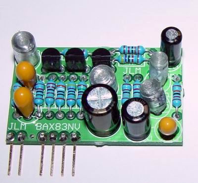
I started laying out the amp block tonight (for the crack of it really). I'm trying to go for something close to the orginal layout but with 0.1" spaced pins off the bottom like the new JLM 283 boards if anyone saw them.

BAX83NV.jpg


I know soundguy mentioned having it all on one PCB but I thought I'd have a go at plugin modules see what gives. I can't find some of the transistors at the obvious Farnell, RS etc, so if anyone has a source of the BFR41, 81 (TO92) and 2N930 (TO-18) that would be great. BFR41 etc seem to be listed as R.F power transistors.

If there is any way we could measure that MF inductor then we would be rolling........

Cheers Tom
 

Latest posts

Back
Top