Calrec PQ 1061

GroupDIY Audio Forum

Help Support GroupDIY Audio Forum:

This site may earn a commission from merchant affiliate links, including eBay, Amazon, and others.
It's slowly coming along, but delivering the movie Happy Feet 2 ( my day job is a visual FX artist ) is gonna keep me busy until next year, so it'll be slow progress for the next month or so sorry!

But I've moved forward with some of the design of the DOAs:

CalrecPQ1061_PCB_v03.jpg
 
OK, I just ordered enough parts to make 4 x 1061's worth of DOA's.
I'll report in the new year on my success/failure in getting them to work as well as they do in the simulations!
 
Keep up the good work! im following your progress,
I have now managed to get hold of a total of 6x 1061's so i think id still be interested to build 2x if your design comes out close enough, otherwise il keep an eye out for 2 more genuine units.
 
Wow awesome! Lets keep in touch then cause that's a great reference point.
Im currently on holidays in Tuscany and some more of Italy until the 9th of December, hence the slow progress on this page, but I intend to hit the ground running quite soon after I get back.
So sorry about the big gap in progress but I've been thinking about it a lot out here in the middle of Italy ;-)
 
OK I have a quick update on this, I've just had a quick squizz at this again, and just designed a pre-amplifier based on just the pre-amp sub-section of the Calrec 1061.
I'm gonna use this as an intro project to making the whole shebang.

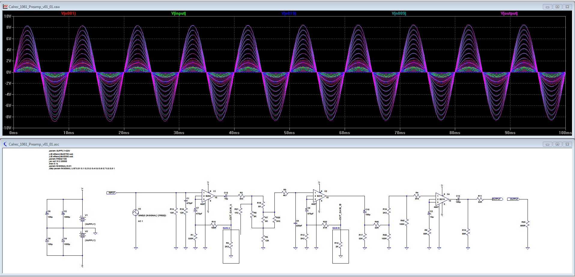
Here it is, and it simulates perfectly (although I still haven't finished improving it yet, since it's an exact replica of the original, which is not necessarily a good thing...., with substitutions like 2 resistors for the small gain trimmer - which will be different obviously on the PCB, and some HPF caps which seem to mess too much with the bass response, which I'd like to change) - 2 gain stages, and then an output driver.

I'd recommend using transformers at input and output, but it doesn't appear that's a requirement, as the B210 DOA can supposedly drive down to 600ohms, and at lower gains, the input should be perfectly fine as is (i.e. line in etc.), so the simulator says "hell yes", you should be able to use the output transformer-free if you wish to do so.

There's an almost infinite amount of gain available here depending on how the gain resistors are wired up (as per the 1061 there's up to 70dB on tap! yet there don't appear to be issues going even higher....), but, more to come soon, this will definitely be an interesting little project, as it can also be unity gain for some nice analog warming too....  However, for those following the API Compressor thread, I'll probably try and finish that first 8)

Calrec1061_Preamp_Sketch_v01.jpg


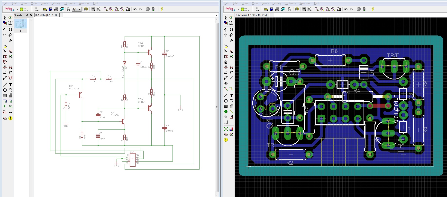
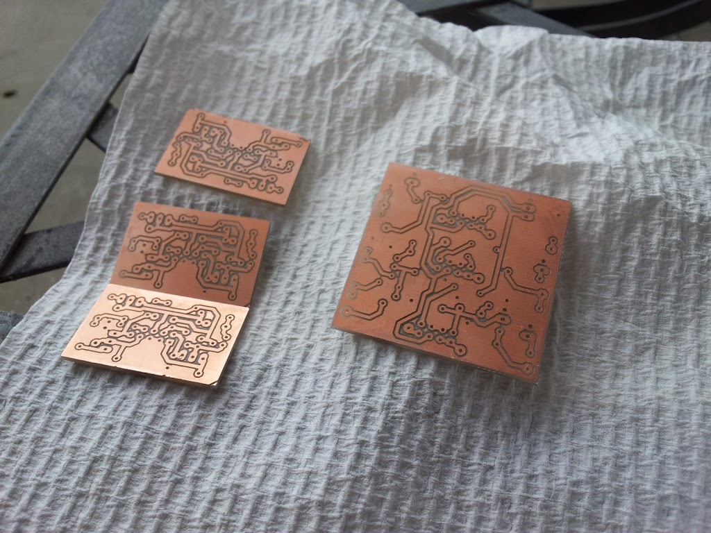
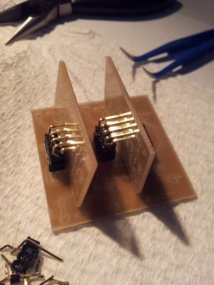
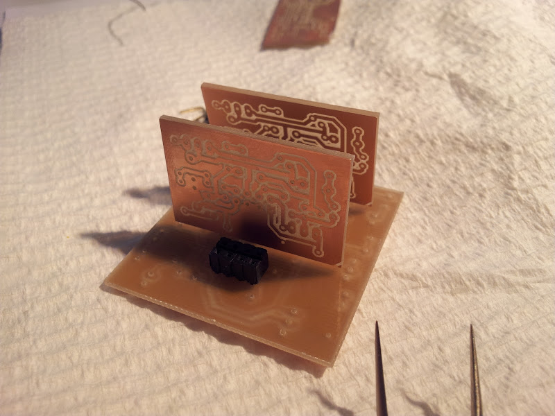
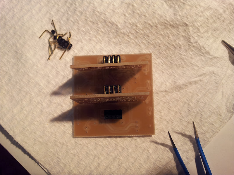
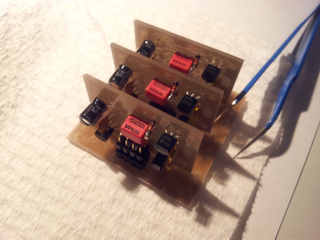
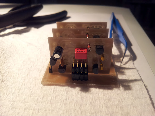
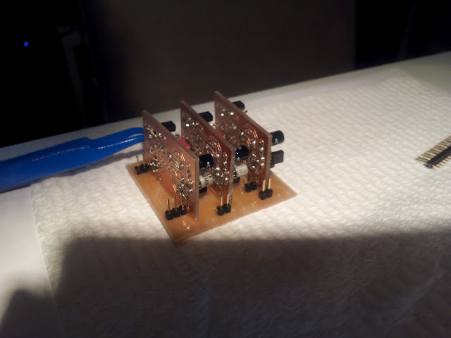
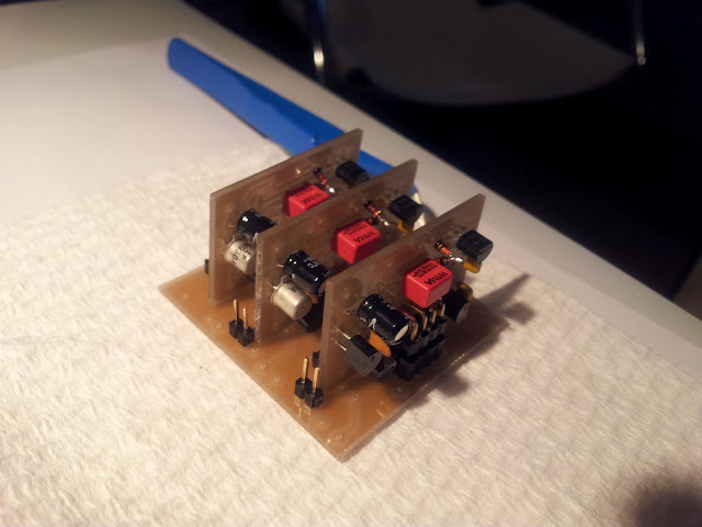
Here is the DOA board that I'm currently happy with too - it's VERY close to the original spec-wise, the only substitution is rather than BFR41 and BFR81 on the output, it uses BC639/BC640, aside from that it's absolutely identical to the original, since the parts are quite easy to come by:

Calrec1061_DOA_Eagle_v01.jpg
 
I know I said I wouldn't get to this for a while, but I lied, so, here is some progress on some test DOA's and a test board for my take on a Calrec PQ1061 microphone pre-amplifier.
I'm having some issues mating the connectors (I keep breaking them as I didn't CNC the holes big enough....) but I'll get there....

Here they are drying outside after an alcoholic wash:
2012-01-28-17.15.53.jpg


Here you can see 2 of the 3 amplification stages being test assembled for fit testing (which isn't going to well, you win some, you lose some....):
2012-01-28-17.38.34.jpg


A different angle to show you the back:
2012-01-28-17.38.52.jpg


And above, where it's clear how spectacularly bad my estimates were for the positions and sizes of just about everything 8) - but it's a test, so I'll force it to work.
Looks like the majority of parts will have to go underneath the board for this particular revision :-\
2012-01-28-17.39.05.jpg
 
Some images of a few bits on the partially populated amp boards (A B202 input stage/1st gain stage, a B210 2nd gain stage, and a B210 output driver):
2012-01-29-00.07.13.jpg

2012-01-29-00.07.40.jpg

2012-01-29-00.08.32.jpg

2012-01-29-00.08.57.jpg
 
DigitalMetal said:
So what happened with this project?  ;)

At the time I was making it I needed a pre-amplifier for the album project I was working on.
The quote from Sowter regarding the input and output transformers I wanted was so insanely high that it immediately stopped the 1061 project.
The result was a complete change of concept and a totally original design that I created here: http://www.groupdiy.com/index.php?topic=49341.0 - which was much cheaper for me to make and fit the bill perfectly.

I still have the PCB's for the PQ1061 daughter board amplifiers, which should work but I never tested them.
Now that you bring this up it would be easy enough for me to plug them in one weekend to a breakboard and see if they smoke themselves or smoke up my audio 8)

The main test board that they plug in to was never finished simply because I messed up the spacing on it and nothing fit. The daughter board concept was sound and they fit into their sockets, but at the time I only had the size-limited demo of Eagle and my need to fit things into the tiny allowed space produced an incorrect result. Now that I have the full version of Eagle I am still keen to one day revisit the design and try again.

It's definitely a project I wish to return to at some point, but there's a lot of stuff that has re-prioritized ahead of it sorry.
 
gyraf said:
Couldn't it just be made with standard Lundahls and home-rolled inductor? Doesn't seem too esoteric at all?

Jakob E.

Absolutely.

In fact I probably could have even made it with the transformers that I ended up using for the other preamp (Ed Anderson 2622 and Ed Anderson 2623-4) without much issue.

At the time the budget the person I was building for didn't support the PQ1061, so I opted for a simpler and cheaper option even though I'd done a lot of the ground work on the design.
I've just parked it temporarily as it got more complex that I could handle at the time. I've learned a LOT since then however.
When I tackle this again (and I will) I want to do it as well as I can, and I still intend to revisit the whole PQ1061 thing one day, but as a personal project.
 
Did anyone suss out the measurements for the inductor L1 04 284 ?
I want to get a quote in Europe.
Thanks Guys.
 
Back
Top