"Crush-n-Blend"

GroupDIY Audio Forum

Help Support GroupDIY Audio Forum:

This site may earn a commission from merchant affiliate links, including eBay, Amazon, and others.
Everytime I see this post coming up I have to reread the last three pages or so to make sense of it....sorry, it's taking to long...I'm tired, need sleeeeep.
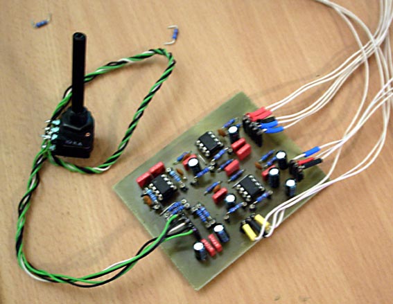
 
Mine still needs some tweaking. The send (or out to comp) isn't sending. BTW, I lifted pins 1, 5 from the INA134s just to see and had some ugly distortion.

ws500_01
 
Just a quick update to the post above. I fixed the send and now it's working pretty well. You could tweak the gain a bit and increase the blend pot value if you were so inclined. I used INA134 for the inputs & a THAT line driver. On the INA134's, I grounded pin 1 and connected pins 5, 6.

And here's some ugly truth:
halfk_blender_proto
 
Denyle Guitars said:
Just a quick update to the post above. I fixed the send and now it's working pretty well. You could tweak the gain a bit and increase the blend pot value if you were so inclined. I used INA134 for the inputs & a THAT line driver. On the INA134's, I grounded pin 1 and connected pins 5, 6.

And here's some ugly truth:

OK! great to see someone did actuallu build one working :)
are there any differences compared to the original schematics?
BTW.. what caps are the 10uf's?
 
OK! great to see someone did actuallu build one working :)
are there any differences compared to the original schematics?

Nothing major. I used what I could find so it's not a part for part copy. Just look at the data sheets for each IC to comfirm the correct pinout.

BTW.. what caps are the 10uf's?

Cornell Dubilier 935
 
Funny, this topic seems to come in waves...so, here's my little progress:

Built test jig and now the input section with straight SSMs works at unity nicely like it should. In process now tracking down what's going on on the output, there seems to be some kind of warfare going on there, distortion but no huge signal.

Check Output-Works. Gain good.

Time for the OPA. OPA works, ok board works.

Provides exactly 9db of gain if you set the OPA to unity with a pair of 1Ks, which is good because it means the board works. Plugged in the pot, works. Toying around with resistor values right now, but basically it just works.

ran it through a transfer function and it is dead linear down to 30Hz, where the caps cause a drop and the phase begins turning up to 60 degrees + by the time you reach DC, but basically everything above that is textbook.

So feel free to etch&build my board, the principle is there and functioning. You might need a little resistor divider on the input in case you hook it up to something that is too steamy, but apart from that it's a functioning bugger. I'm gonna screw around a little more until I get unity gain from in to out.

Then it's time to build a VCA version.

 
Getting a little graphy here with that pot divider, if I am making sense
the divider should have a gain of Vout=Vin*R2/(R1+R2),
then set Vin to 1 you get this:

gainplotsmall.jpg


The bigger you set R1, the flatter the graph gets, almost down to a linear
sorta thing. Obviously I'm gonna try some stuff out here first, but in general,
what I'm asking myself right now is whether it would be best to smash it down
to almost a linear approximation, that giving you the same level at the output
at all times (just about).

The bottom line there is 4:1, looks doable...
 
Okay, here we go. With the basic idea in mind to stick this thing
into a box, I decided to leave out the balancing elements and just
get a buffered in and the crush tail, using old faithful 5532s to keep
the cost manageable. All in all, you can build it for about 10€.

I call it "internal crush"

intcrush.jpg


Here is the schematic

I decided to go with the 4:1 ratio but now looking at it and (if I got this
right) by the output opamp's input being at ground, we end up with the
pot in parallel (?) with r2, r4 etc and thus get around 8:1, changed
the output feedback r to 91K and now gain is unity to exactly .1 dB.

If you want to etch & build it, here you go:

Components

Photopositive 1200 dpi

And just for Kicks, I did a little crossfade test:

Bing&Dimmu


I quite like the behavior of the crossfade law with this resistor
setup, don't know if there might be some hidden problems
with using 91Ks and such, but it definitely works. Ah BOM, yeah,
just grab 3 5532s and their sockets and your trusty box of resistors,
we have like 8 10Ks or 22Ks or what have you for input, then four
39Ks, four 10Ks and two 91Ks. Pot is standard 2x10K lin and electrolytics,
well, I wrote 22u but just stick in what you feel is right. Additionally,
there's the 100n WIMAs in there. Oh yeah, and those 20p's there,
not sure what's ideal, I built mine with 33p's.

I think that's it. If anybody has suggestions, be welcome.

Have fun  :D

Lukas
 
Well, yeah, but it will probably do just about any kind of a-b mixing for you by design, as it is approx. unity from input to output. Definitely designed for the GSSL, though, with the 5532s being part of the SSL sound.
 
thanks !

i'm really glad you've shared that with the community ;)

i'm ready to build it !!!

where did you hook up (plug) your internal crush inside the GSSL ?

is it possible to pick up signal before symmetrisation for the output / after de-symmetrisation for the input, without modifying the internal impedances ... ?
 
Haven't stuck it into the ssl yet, it's fresh off the bench. What I can guarantee is that it works, but rest assured I will be installing it into mine here soon enough. Do you etch?
 
no.
but there's a shop in here wich do it for 1€/square centimeter, tracks ready to solder. but you have to do the holes yourself (i'm missing the word - you get me right ?)
not really cheap... but it helps when you don't want to do 10 cards.

nice work indeed. i think i'm gonna do one in an external box. could be useful for A/B comparison & blending FX...
 
What, one Euro per square centimeter AND you have to drill the holes yourself?

PM me your address, dear, we can do that a LOT cheaper ;)

As far as the internal impedances go, here's my thinking:

Dry input - install right before the input cap. Thinking here is
that since ops have theoretical 0 output impedance, basically
it would just make the input debal work a little harder.

Output/wet is a little trickier, from what I can tell the first
amp sets the gain and the second flips at unity. Polarity being
the issue here, I recommend leaving the first output amp
where it is and grabbing the signal from there.

Note that the pinout is backwards on the schematic, the
first output bal amp is gateswapped with the second
(pins 5,6,7 rather than 1,2,3) on the board.

Since the first inverting stage delivers a + signal and
the lil' crusher flips twice, the ideal place to stick it in
imho would be right after the 15K feedback resistor, cutting
the 100R and 10K resistors out at the side facing the output
of the first amp (pin 1 in the schematic, pin 7 on the
PCB). That would be our "get in there"-point, letting
the second output amp do the flipping and we're home.

I am not firm enough in the theory to discern the difference
between me holding my output noninv pin to ground and
the ssl's being held at 10K to ground, but I don't think
(this is guessing) that it should be an issue.
 
:D

i think i get you.
as i told you, i don't have the knowledge to help you. maybe ask jakob on that ?

one thing i have to consider, is that every time i have to solder twice on the SSL pcb (desolder a resistor for exemple), the tracks get destroyed, even if i'm very fast...

so if i have to plug it to the board... i have to be sure of what i'm doing.

question : with the ssl tech version with symmetry, we could plug this on the in's & out's whithout going to the board ?

if you go doing pcb (i'm sure a lot of people are interrested in that "crush & blend" module), wouldn't be better to go for a symmetric version, so we can use it externaly in studio environement without any risk of signal quality loss ?
(hum, hum, i'm a bit anoyed to point that out now, as you already finished the job...)
i hope i didn't missunderstood something...

 
Not at all, In the meantime I have three flavors of board designs.

Two are balanced and one is the unbalanced version up there.

Let me tell the story...

First, I saw the CnB thread, and of course wanted to build me
one, and since I'm quite boardish went and designed one, but
based on the SSL's balanced I/O for saving cost (though I wouldn't
do it with a TL anymore). That distorted like heck and though
I'm sure that's more to do with resistors and gain ratios, I do
have to go over it before I put it up for order.

Thus confused, I built one to the exact schematic of Keith, and
in the mean time got that working right good as a crossfader,
out and in of the 2882 Halo. By that time I decided to see if
I could simplify to get an unbal version for in the box, and that's
the one up above. It just suits me more to have one less chippedy
to send my signal through, plus at 10 Euros for the components
you can box three of these before you get the balanced ssm one
sourced.

Concerning soldering around: There's this trick, if you can get
yourself some DIL or SIL sockets with turned pins you can butcher
them for the individual pins and solder them in where the resistors
go. Now you have a stick-n-pull version that doesn't entail soldering,
and is great for figuring out gain ratios. You can see that in the pic
of the board.

I will try to box it sometime this weekend, as well as the bal version,
and then I can tell you how I did it.

Regards,

Lukas
 
livingnote said:
And just for Kicks, I did a little crossfade test:

Bing&Dimmu

Have fun  :D

Lukas


Man! That was quite a wake-up moment for me!  ;D

Good job by the way. Very interesting.  But I cannot build it for my GSSL, better luck next time.  :)
 
Well you can give me your address if you want one of those "free sample" ones, it's a good thing to get experimenting, I still want to make a nicer board here for the bal ones (really curious about the 5532 bal one once that works right).

L
 

Latest posts

Back
Top