D-AOC PCBs - the building and help Thread

GroupDIY Audio Forum

Help Support GroupDIY Audio Forum:

This site may earn a commission from merchant affiliate links, including eBay, Amazon, and others.
HI Unit-8,
First of all many compliments for your build impressive !!!
Since i build my unit in 2011 , now i thought to modify the unit with stepped switch instead of potentiometer
I saw your unit and i noticed that you mount two elma for the compression stage and 4 lorlin on the pcb for the input output stage .
I'm right or not ?
Can you explain me how you proceed and if you can help me for the pcb that you have built ?


Unit-8 said:
Hi all,

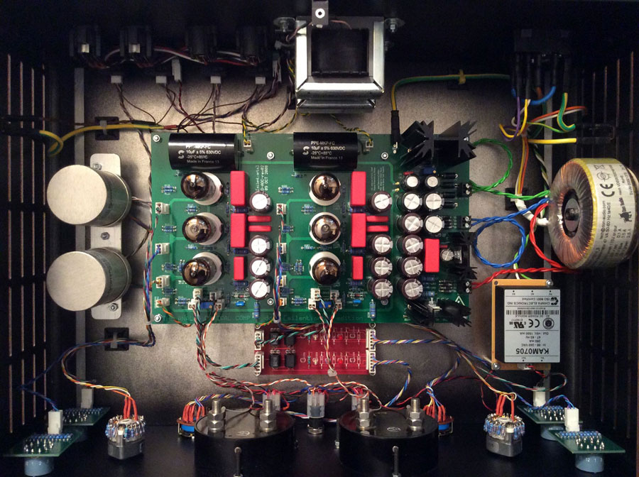
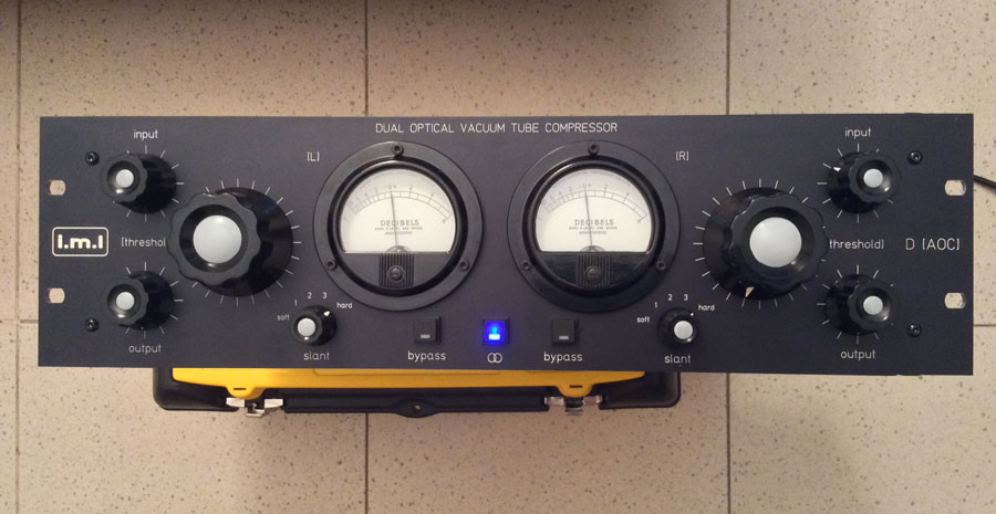
After completing all tests and had a long burn-in for tubes as well as for audio transformers i confirm the quality of this compressor. I really love it!
Here are a few pictures.
daoc1.jpg


daoc2.jpg
 
Unit-8 said:
Hi all,

After completing all tests and had a long burn-in for tubes as well as for audio transformers i confirm the quality of this compressor. I really love it!
Here are a few pictures.

daoc1.jpg

Beautiful.  What is the red pcb?
 
Hello All ,
                    Finally getting back to DIY and this project , couple questions ....  I have a couple 62v 5w zeners left from D-LA2A , was hoping they would work in this project for same purpose in place of Neon lamp  ?

    also I am doing the Kubi mod and happen to have some 470nf  630v axial Solens  mistakenly ordered years ago and was wondering since I can stand them on end, they physically fit in the Cx04 positions.  Looking at pictures of finished units it seems most people used the 100nf or 220nf , just wondering if its worth putting these in this spot now as I have them on hand.

  Thanks in advance    :) 

....  Beautiful work Unit-8    ;)
 
FWIW I was able to manage fitting 1uF @ C102, C104, C105

There are power resistors underneath the caps. If it gets toasty I plan to remove the resistors @ R11 & R7 & R18 and stand them on end/vertically so they don't fry the undersides of the oversized capacitors.

There was talk of a pole in the sidechain which caused LESS gain reduction with more low end signal, which is what I'm trying to avoid.
 
MicDaddy said:
FWIW I was able to manage fitting 1uF @ C102, C104, C105

There are power resistors underneath the caps. If it gets toasty I plan to remove the resistors @ R11 & R7 & R18 and stand them on end/vertically so they don't fry the undersides of the oversized capacitors.

There was talk of a pole in the sidechain which caused LESS gain reduction with more low end signal, which is what I'm trying to avoid.


  THANKS  !!    I was going to do that , but thought the same thing about the heat from the high watt resistors.  in the notes for the "kubi advanced version"  it says "100nF is too small for many applications. Even worse: If you push the compressor harder, more current goes though the diodes and the resistance lowers so that less compression happens"  so I think you're good , I just had not seen or heard of anyone actually putting in a higher value than 220nf , so I'll put the 470nf's in and go with that !!  :)
 
There are power resistors underneath the caps. If it gets toasty I plan to remove the resistors @ R11 & R7 & R18 and stand them on end/vertically so they don't fry the undersides of the oversized capacitors.

How about soldering the resistors from the underside of the board?
 
Ha !!  I was thinking that also but still concerned about PCB blocking heat dissipation, don't  know how hot they really get. I can fit the 470uf on end with plenty of clearance from resistors. I'm going to mock up checking clearance of resistors on bottom of PCB and floor of case.
 
Trapping the heat under the pcb isn't something I wanted to do.  If those resistors get hot then there's not much chance for convection away from the pcb, in fact the board I would think equilibrium would cause the board to heat up substantially from 6x 2W heaters below, maybe it would work.

There's also the issue of vertically arranging the resistors as aren't they now an effective antenna?

 
ok ... silly newb question ,
                                                          I've never used the mica isolation kits for the voltage regulators before nor the specified heat sinks.
  The insulator instructions seem strait forward enough , but do you / should you use thermal paste on the mica insulator ?? .. or does that now make it electrically conductive ? ...  and the thick pins on the heat sinks that go through the PCB , do you solder them in ??  I notice pad where the pins go through


  Thanks in Advance  :)
 
Ok, so I checked out Small Bear. Are these Vactrols going to work?

http://smallbear-electronics.mybigcommerce.com/photocouplers-macron-mi1210cle-r/

Also, does anyone have a current source for a Power Transformer?
 
justinheronmusic said:
Ok, so I checked out Small Bear. Are these Vactrols going to work?
http://smallbear-electronics.mybigcommerce.com/photocouplers-macron-mi1210cle-r/
no. even if we would live with total different characteristics it is not dual element.
 

Latest posts

Back
Top