Maybe try swapping it back & seeing if there is a roll off with your other attenuator. At least that way you know if it's that or not.
You are using an out of date browser. It may not display this or other websites correctly.
You should upgrade or use an alternative browser.
You should upgrade or use an alternative browser.
EMI RS124
- Thread starter ed rees
- Start date


Help Support GroupDIY Audio Forum:
This site may earn a commission from merchant affiliate
links, including eBay, Amazon, and others.
letterbeacon
Well-known member
I swapped the old attenuator back in and I get the same low cut.
I’ve gone through the and ticked off all the connections on the schematic -they all seem correct.
The voltages are all dead on, give or take a volt or two.
I have the Sowter 436 output TX wired for 600ohms, as per the Altec 436 schematic, but I’ve just noticed the secondary on the output TX on RS124 appears to be wired slightly differently. I suppose that could be a possibility...
I just recieved my Sowter outs for my pair yesterday. Whilst I am having problems getting any compression I don't have any Low cut issues at all, I'm still using the 2 x 300 ohm with a 1Klog pot as the out put attenuator & there are no sissues with this.
I got some 200uA meters from china, which also arrived yesterday, but they don't zero without a trimmer added to them. WIthout the trimmer they are pegged to the right,
My issue is they same as before, If I wind the input signal up, I get some small amount compression happening, but the more I wind it up the meter goes back up to zero. This is despite the side chain signal dropping to -10v to -15v.
More investigation after I have walked my dogs !
letterbeacon
Well-known member
Rob Flinn said:I just recieved my Sowter outs for my pair yesterday. Whilst I am having problems getting any compression I don't have any Low cut issues at all, I'm still using the 2 x 300 ohm with a 1Klog pot as the out put attenuator & there are no sissues with this.
Yes I noticed no difference in the low cut whether it was the 1K log pot or the 600ohm attenuator I had in there.
I've tried wiring up the Sowter outputs the 436 way and the RS124 way and there's no difference there either. I assume the RS124 way is wired up for 150ohm impedance. Which way do you have your outputs wired up?
Have you included R17 in your builds? I haven't as I assumed that was something specific to EMI's pad.
letterbeacon said:Yes I noticed no difference in the low cut whether it was the 1K log pot or the 600ohm attenuator I had in there.
I've tried wiring up the Sowter outputs the 436 way and the RS124 way and there's no difference there either. I assume the RS124 way is wired up for 150ohm impedance. Which way do you have your outputs wired up?
Have you included R17 in your builds? I haven't as I assumed that was something specific to EMI's pad.
No I don't use R17. I believe it's there as part of the constant impedance network so the output always sees 150R at least. I have my outs wired as 600R, & using my attenuator the 2 x 300R ensure that the output always sees at least 600R even if turned all the awy down,
letterbeacon
Well-known member
This might seem like a stupid question (but I'm beyond asking stupid questions now), but the input pot - I have it wired so when it is fully clockwise (ie. at maximum) I have both pots wired so that the output from the input TX are connected straight to pins 2 and 7 of the first tube.
That's correct, right?
That's correct, right?


letterbeacon said:This might seem like a stupid question (but I'm beyond asking stupid questions now), but the input pot - I have it wired so when it is fully clockwise (ie. at maximum) I have both pots wired so that the output from the input TX are connected straight to pins 2 and 7 of the first tube.
That's correct, right?
From the input xlr pins 2 & 3 connect to position 3 of the pot (the left hand tag if you are looking at it from the back. Pin 2 xlr to one of the wafers of pot & pin 3 of the xlr to the other wafer of pot.
For the middle position of the pot 1 wafer connects to pin 2 of v1 & the other wafer connected to pin 7 of v1,
Looking at the back of the pot both right hand tags connect to the C4/R12 junction
letterbeacon
Well-known member
Rob Flinn said:From the input xlr pins 2 & 3 connect to position 3 of the pot (the left hand tag if you are looking at it from the back. Pin 2 xlr to one of the wafers of pot & pin 3 of the xlr to the other wafer of pot.
For the middle position of the pot 1 wafer connects to pin 2 of v1 & the other wafer connected to pin 7 of v1,
Looking at the back of the pot both right hand tags connect to the C4/R12 junction
I have my input TX between the XLR in and the input pot, and you mean position 3 being the right hand tag when looking from behind, right?
If so, it looks like I've got my input pot wired up correctly.
XLR Pin 2 > blue wire on Peerless IP TX > pin 3 of 1st wafer on input pot
XLR Pin 3 > red wire on Peerless IPTX > pin 3 of 2nd wafer on input pot
Pin 2 (middle pin) 1st wafer of input pot > pin 2 on V1
Pin 2 (middle pin) 2nd wafer of input pot > pin 7 on V1
Pin 1 (left hand pin from the back) 1st wafer of input pot connected with pin1 on 2nd wafer, which are then connected to 33k/ .5uf cap.
Yes, that sounds correct.
I kind of have mine working, but it's not really working quite right. I had to use a 220r trimmer for R25, I have the meter slugged with another 220r trimmer instead of R8. Dicking around with these presets I can get 1.1v on the wiper of the balance pot & the meter sitting at around zero. However, with this all set up the anodes of V1 are only at around 55v and not the 75v specced on the diagram although the h.t off R13 is bang on 195v as per the diagram.
With a 0dBv signal & the input pot all the way up I get a control signal of around -7.5v, but at this point the audio is not useable as it's distorting in a bad way. The max useable gain reduction seems to be when I turn the input pot up so the side chain signal is -7v. If I go beyond this point the control signal increases but distortion takes over, and the meter actually shows less G.R.
I have a meter that has a scale from 0 to 200uA. If I set the zero point to be 200uA, when I have max useable gain reduction (sidechain signal -7v) the meter drops to display about 125uA. I can measure the max gain reduction to be around -7dB.
I was certainly expecting the meter to move a bit more, but comparing to the scale of the original the amount of movement seems to concur.
I don't know if it's possible for anyone else who has built or know this box to verify whether this sounds about right ? i.e Can you only get -7db gain reduction before it sounds bad, & if you go beyond this point does the meter start to climb again ?
Also the useable gain reduction is nothing like -7dB. Even using the balnce control to minimise thumps I can't do more than 2-3dB GR. I'm guessing this isn't working right .....
Winston O'Boogie said:Hey Rob,
when using a 6BC8 valve, I typically saw a little under 20dB of reduction before things began crapping out. Switching to a 6ES8 would get that above 20dB reduction. At idle, anodes were about 75V with a 6BC8 and 55V with the ES8.
What's your anode voltage at the point of crapping out, has it hit the rail by then?
Hi John, thanks for reesponding.
I worked it out. For some reason I had connected the c.t of input transformer secondary to ground & this was really slugging the side chain.
I worked this out from the following.
If I pulled the diode the amp flaked out at roughly the same input level. If I connect a bench psu to create a negative sidechain signal I can turn the amp to the point where it below flakey I can wind a control signal of -16v and it compresses a lot, ecc189 anodes hit 186v & signal is kosher. It therefore appears that the amp part is good & therefore I'm guessing something is happening to screw with my sidechain signal or weaken it somehow.
Pic attached
Attachments

Winston OBoogie
Well-known member
OK yeah that sounds good as far as the amplifier.
Using an ECC189, your anode voltages of about 55V at idle and 186V with -16V grid bias sounds pretty much spot on with what I remember from building this circuit.
Thanks for the pic, it's a bit hard to see anything that might be the issue with your side-chain signal but, I daresay, you'll find it")
Using an ECC189, your anode voltages of about 55V at idle and 186V with -16V grid bias sounds pretty much spot on with what I remember from building this circuit.
Thanks for the pic, it's a bit hard to see anything that might be the issue with your side-chain signal but, I daresay, you'll find it
letterbeacon
Well-known member
I’m still stuck on my RS124 having a low cut filter applied across the amp.
Do you think it could be the .022uf coupling caps that go between V1 and V2? I’ve got some NOS Russian PIO caps there, but can replace with new orange drops.
They’re a bit of a pain to get to so id appreciate it if someone could advise if it’s worth doing before i do it!
Edit -I did it anyway, but to no avail. I get the same behaviour with the new capacitors in.
If anyone has any suggestions, they would be much appreciated!
They’re a bit of a pain to get to so id appreciate it if someone could advise if it’s worth doing before i do it!
Edit -I did it anyway, but to no avail. I get the same behaviour with the new capacitors in.
If anyone has any suggestions, they would be much appreciated!
letterbeacon said:I’m still stuck on my RS124 having a low cut filter applied across the amp.
I now have one of my boxes working correctly and it sounds very nice so keep at it, you will like itwhen you get it going. It definitely doesn't show any LF roll off.
letterbeacon
Well-known member
Winston O'Boogie said:Heya,
Do you hear a lack of low end or is this just something you've measured so far?
The graph you posted earlier looks to have weighting applied to it, is there a way you can test with a sine sweep instead of white noise?
I can definitely hear the lack of low end -anything I put through it sounds incredibly tinny.
Th
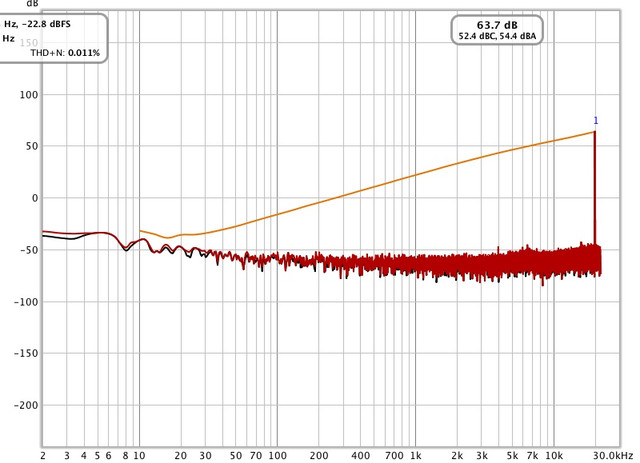
This is with the diode tube taken out, as I know there's something wrong with the side chain, but I want to sort out the amp for now.
Both the input control and the attenuator are fully clockwise - i.e. on max.
I'm using the original Peerless input TX and the Sowter output TX.
I now have one of my boxes working correctly and it sounds very nice so keep at it, you will like itwhen you get it going. It definitely doesn't show any LF roll off.
Congrats Rob - what was the problem with yours?
letterbeacon
Well-known member
This is another sweep I've just done, this time after I've calibrated my sound card with REW:

So you can see something is really off. The dotted line is, I think, the sweep of my soundcard.
So you can see something is really off. The dotted line is, I think, the sweep of my soundcard.
I have both boxes working now. Both stupid mistakes on my part.
unit 1. I somehow had a connection from the pin 1's of the input pot to ground. This was loading the side chain in a weird way.
unit 2. I had the release switch wired 1 step out round the switch. This was making the release non existant.
If your unit is sounding incredibly tinny are you sure you don't have the output or input 1 legged ? That is normally what makes things sound tinny.
John thanks for your help with this. One more question: I'm trying to get the neon oscillator going, I have 60v neons & the voltage divider is giving me about 126v but it's not happening. Could you tell me if Resistor in parallel with the 0.02u cap is a 3M3 ? It's a bit unclear on the diagram.
Winston OBoogie
Well-known member
Rob Flinn said:Could you tell me if Resistor in parallel with the 0.02u cap is a 3M3 ? It's a bit unclear on the diagram.
Hey Rob,
glad you got the units working for the most part.
Yes, the // resistor is a 3M3. Almost there...
letterbeacon
Well-known member
Will do! I'm tempted to break it down and start the amp again, it shouldn't take too long to do as there aren't many parts. Think I'll make it on turret board rather than point to point, as it'll be easier to debug.
Rob - out of interest, did you have the input pot before or after the input tx? I've got mine after, as in the schematic, but from re-reading this thread it seems some people have better luck with it before the input TX.
Rob - out of interest, did you have the input pot before or after the input tx? I've got mine after, as in the schematic, but from re-reading this thread it seems some people have better luck with it before the input TX.
letterbeacon said:Rob - out of interest, did you have the input pot before or after the input tx? I've got mine after, as in the schematic, but from re-reading this thread it seems some people have better luck with it before the input TX.
My pair are both wired exactly as in the diagram, apart from I use a pair of trimmers to set the 1.1v bias & zero the meter. The only reason for this is that despite buying some supposedly 200uA meters (from China) I couldn't get the bias right & meter to zero.
letterbeacon
Well-known member
I've rebuilt the amp and side chain on a tag board, and it's much neater now so hopefully easier to debug. I've left the power supply point to point as that seems to be working fine.
It still isn't working correctly, but in a slightly different way to how it was wrong before - I get a very thin signal still, but when the input pot is at about 10 o'clock, it gets louder, but sounds garbled. Almost as if it's being FM'd. I don't have the diode tube in at the moment, so only the amp is in circuit. I've only just finished the tag board, so haven't had a chance to do any proper debugging yet.
One thing I did want to ask though is the input pot wiring. Here is how I have it set up at the moment - the diagram shows the pot fully open/ counter-clockwise. Is this correct?
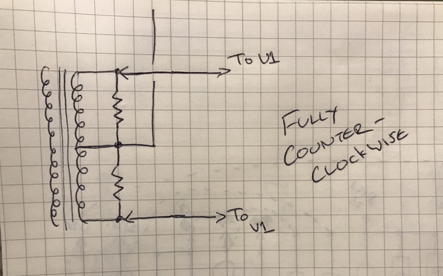
Attachments

Similar threads
- Replies
- 4
- Views
- 627