Slenderchap
Well-known member
I can turn them back on in the on-line store ... but there will be a lead time as we have run out of some stuff.


And since I'm generating so much business for him, my two kits get a discount!!Agreed, i was hoping to get a pair too @Slenderchap
")
And your work is about as good as it gets.Thanks for the link Winetree and Bo Deadly.
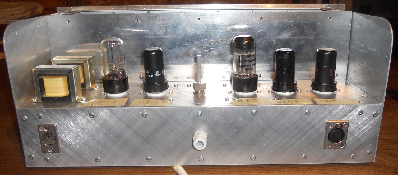
The object of these "from scratch" projects has always been to make them point to point and to avoid pcb's. I try to make them as they used to be made and with materials that anyone can purchase. The idea is to encourage people to try for themselves, as I understand it, that is what GroupDIY was all about. I know that many people like kits because someone else has hopefully done all the difficult stuff for them, nothing wrong with that. My photo is 22 years old so this is also a record of soon to be forgotten arts and crafts.
best
DaveP
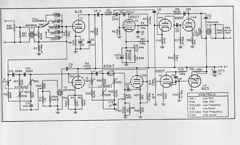
Hi Dave, while "studiing" the schematic of the 627 - which Inductor L1 on the primary winding of the ungaped T3 15k/600 will you use? The original was a 300Hy 5mA UTC S23 as far I could find in the database. Any replacements out there?...Thanks for the link Winetree and Bo Deadly.
The object of these "from scratch" projects has always been to make them point to point and to avoid pcb's. I try to make them as they used to be made and with materials that anyone can purchase. The idea is to encourage people to try for themselves, as I understand it, that is what GroupDIY was all about. I know that many people like kits because someone else has hopefully done all the difficult stuff for them, nothing wrong with that. My photo is 22 years old so this is also a record of soon to be forgotten arts and crafts.
best
DaveP

Dave, great!!! I think I will also do this build PTP. Super affordable idea with the Hammond choke in series....Hi Herbert,
I will try one Hammond 156C which has 150H at 8mA, but if that loses some low end I will use two of them in series.
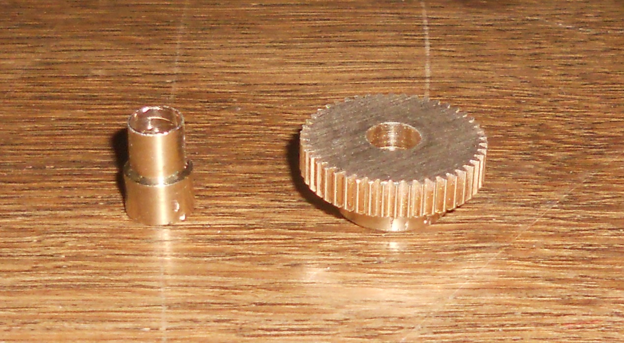
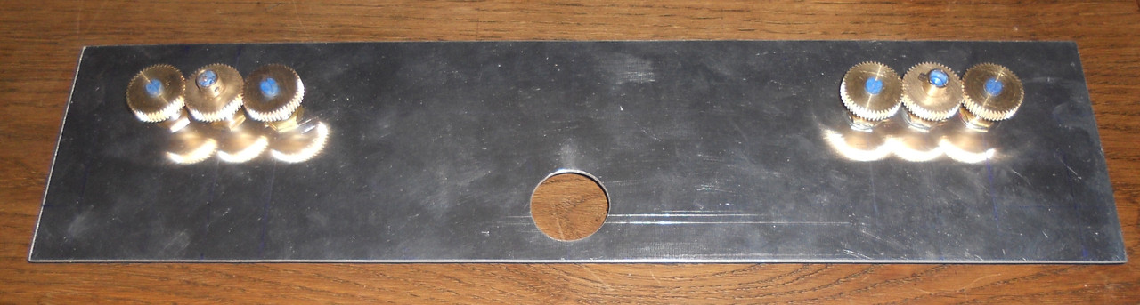
I imagine the triple pots were originally wire-wound so they will be linear. Log pots have about 3 or 4 linear sections so it is more difficult to get them to match up in a circuit like this.
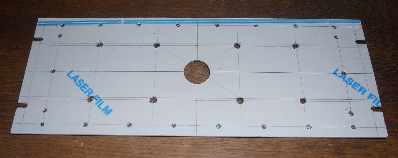
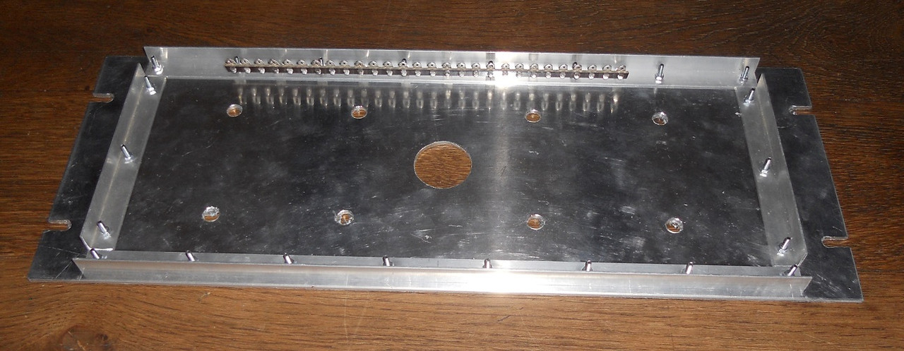
I had to do another job for a friend, but now I am back on the case and the chassis is being put together, more pics soon.
best
DaveP

 ... "self" combining 100k and 47k "Gangs" on Quadpot Shafts together...?.. and the same with 4K7 and 10k's. ... Or your Idea...
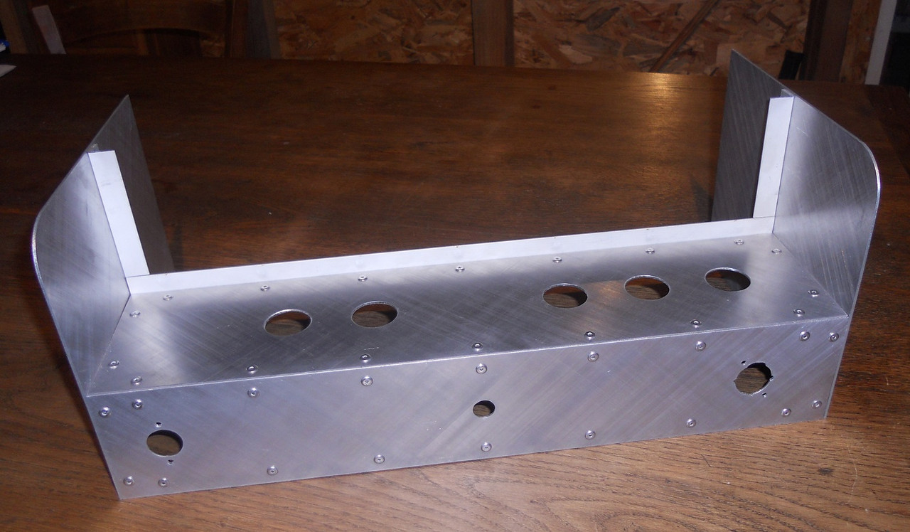
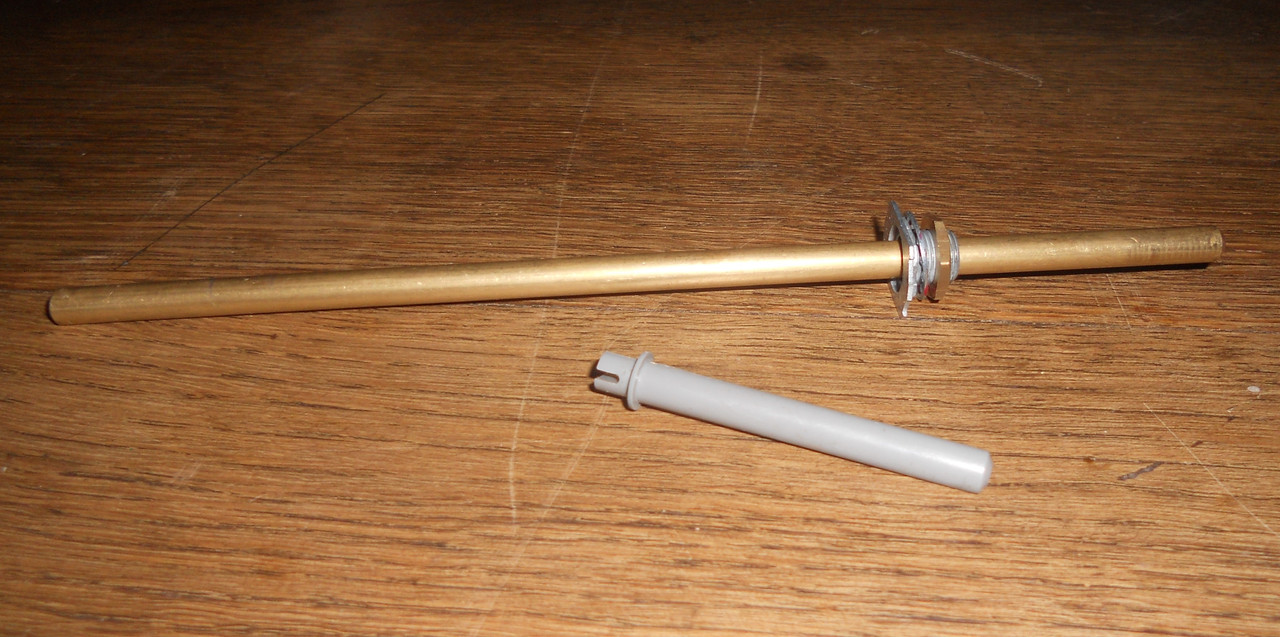
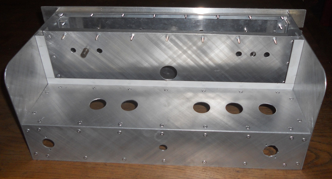
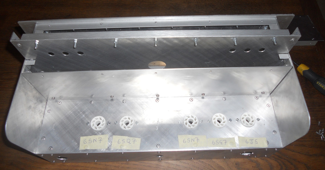
As always, I enjoy watching your builds.This shows the chassis partially assembled to fit the internal panel for the triple pots and the tube base for the 6E5.
I have to sort out the right angle for the 6E5 so I have not yet fitted its tube base. The tube passes through the hole on the front panel to locate on the tube base.
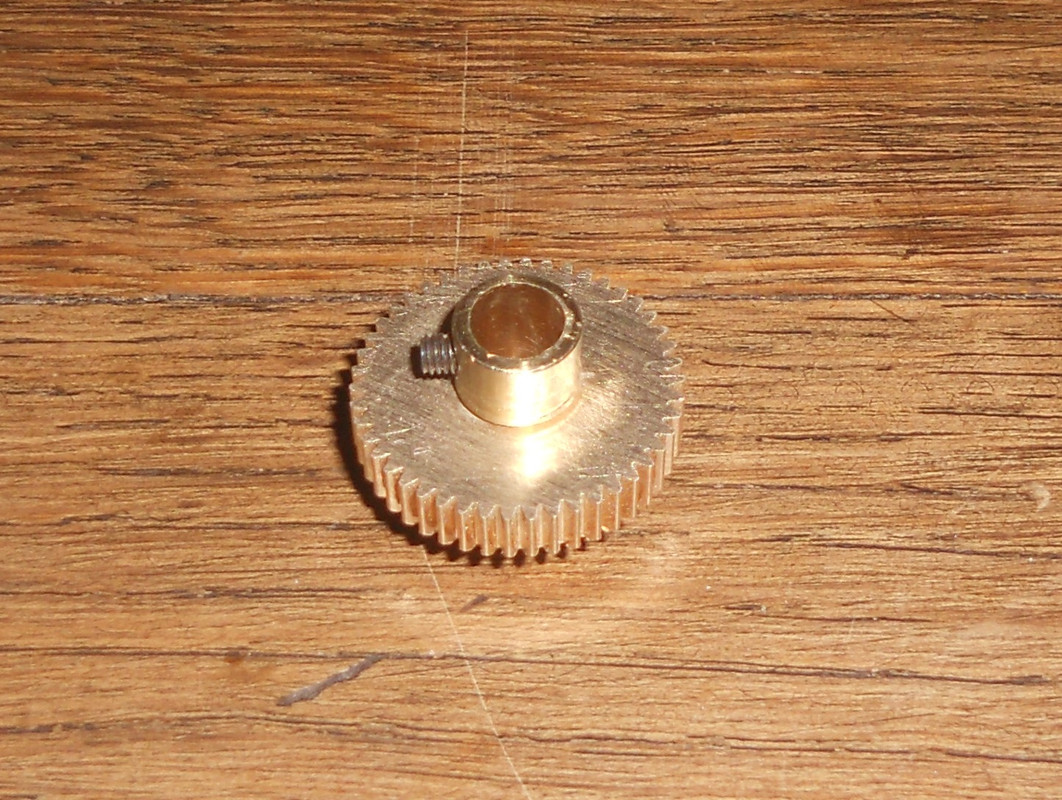
The cogs have to be fitted with the outer pots at maximum and the inner pot at minimum. This is because they revolve anti-clockwise, I have to remember to wire them in reverse too.
Now this is done I can finish all the rest of the panels
Best
DaveP

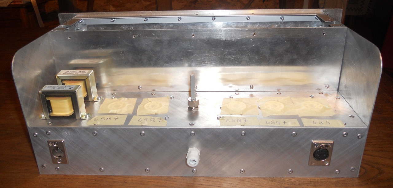
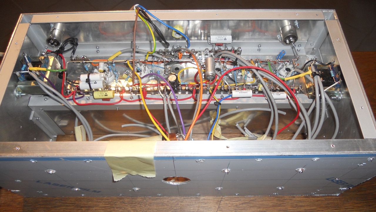
Looks excellent. I also bought 2*150H Hammond Chokes for serial use per channel. They were cheap, about 14 Euro pP. I also think facing the windings of these chokes could cause small interferences. I will try them mounted in series or in 45° angle. At least I made good experiences mounting 8 unshielded In/Out/Interstageaudio edcors for a 670 build in 45° angle position in a 4U 19 inch case sidewall.I have found a home for the large components keeping the input away from the output stage and mounting the chokes in a right angle plane to the IPT &OPT. I decided to use two chokes to be on the safe side to get 300 H in series. I am not sure which way to wire them yet, any ideas? They are facing each other so the external fields may interact. The central pot is R33 which sets the level of the indicator tube.
I am waiting for the second delivery from RS (the first got here OK) the switch for the low cut got lost because they only put on half my address. It really annoys me that they split the deliveries, which effectively doubles the carbon footprint. Have you noticed that we can’t contact delivery companies to correct addresses because their system won’t allow it, I guess for security reasons, that’s progress for you!
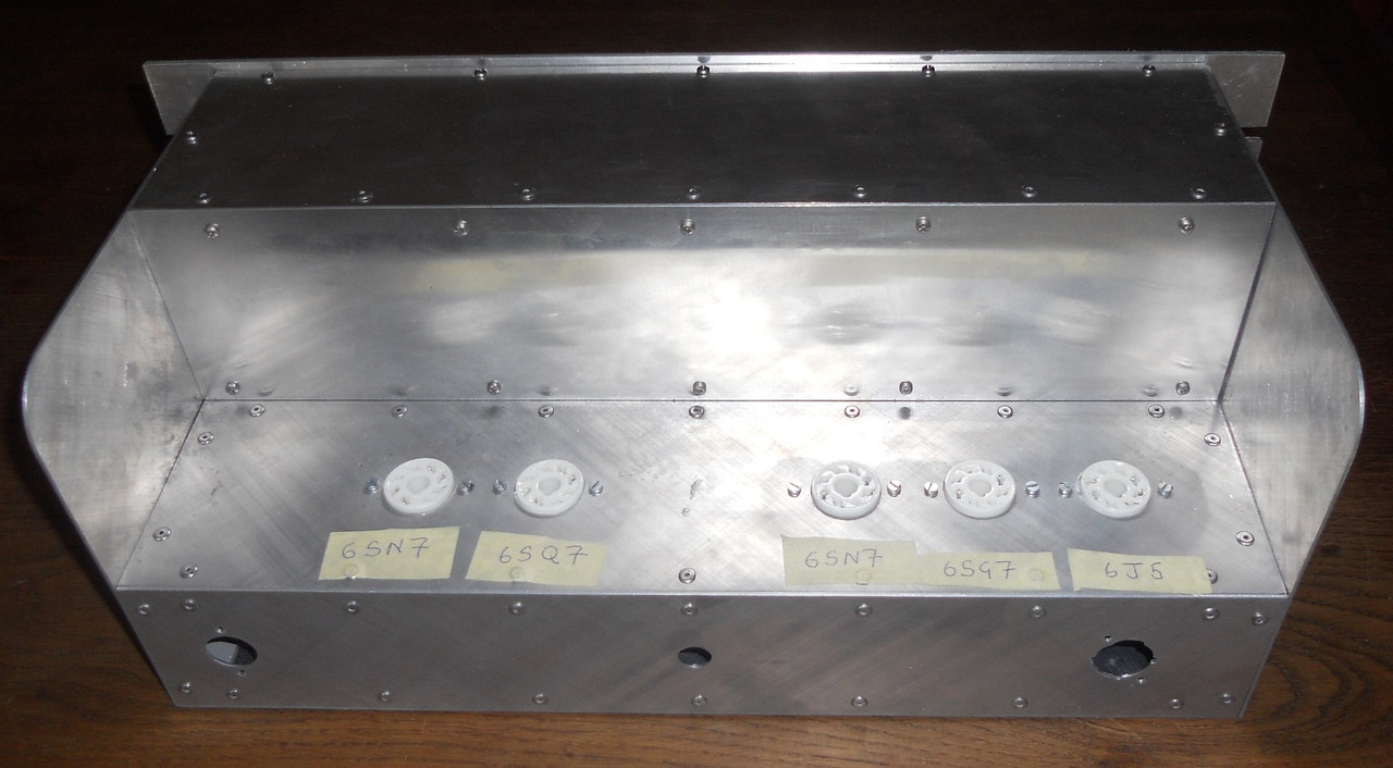
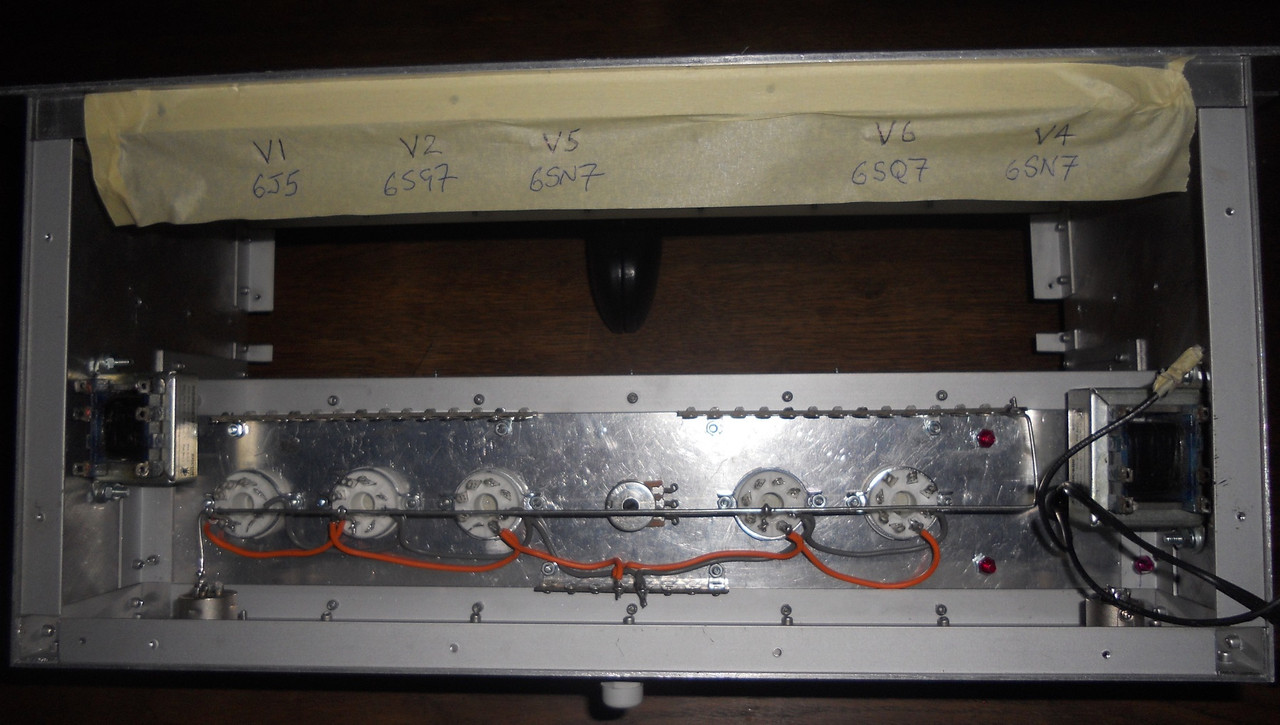
The heaters are now wired up (except 6E5) and the busbar is now in place with the chassis connection only at the input socket. The tag strips allow me to start to add the resistors and capacitors next.
Best
DaveP