Fairchild 627 from scratch

GroupDIY Audio Forum

Help Support GroupDIY Audio Forum:

This site may earn a commission from merchant affiliate links, including eBay, Amazon, and others.
It has been a while since the last post as I had to solve an alignment problem with the pot extensions.
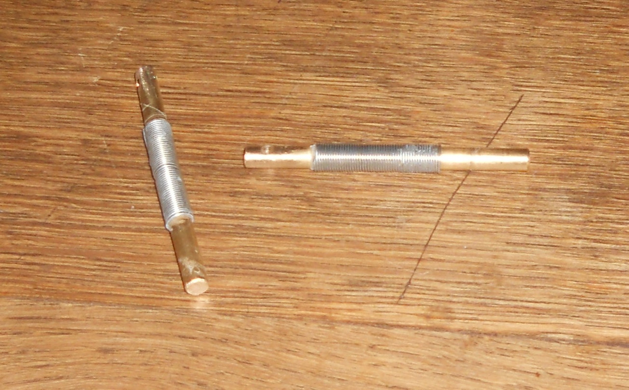


I cut the rods in half and joined them with a tight fitting spring glued on; this allows a nice smooth movement.

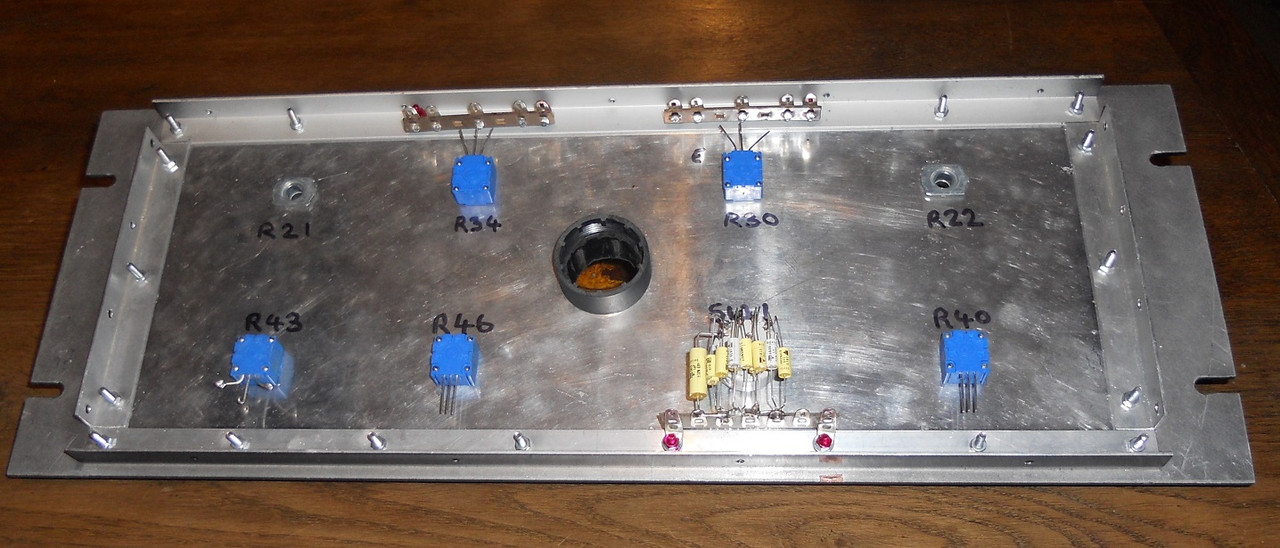
I roughened the surface of the front panel and applied two coats of aluminium primer.
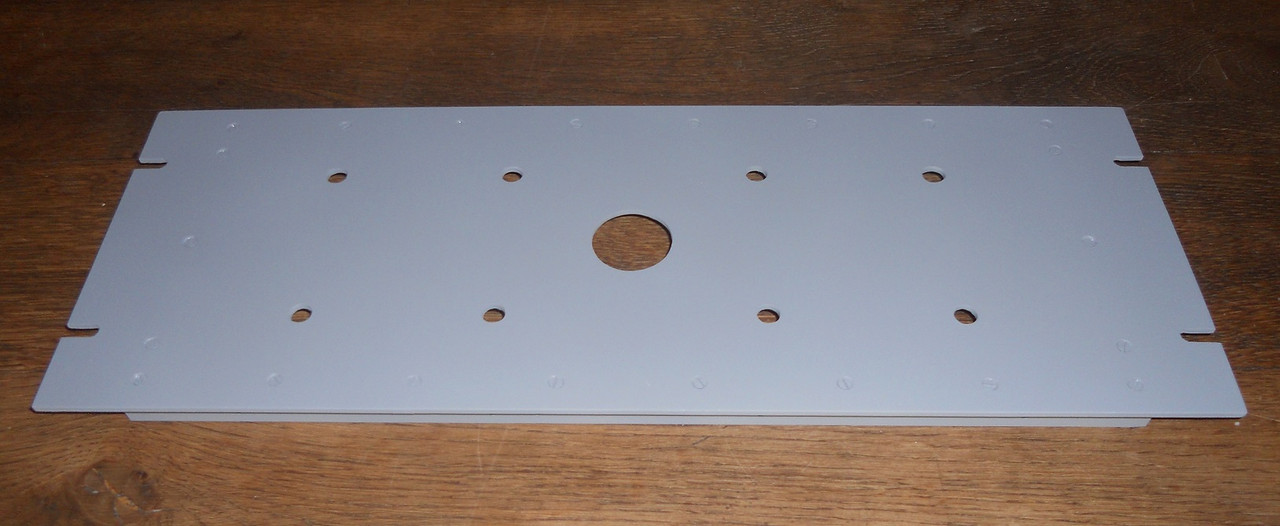


The next step is to apply some matte black before the lettering.

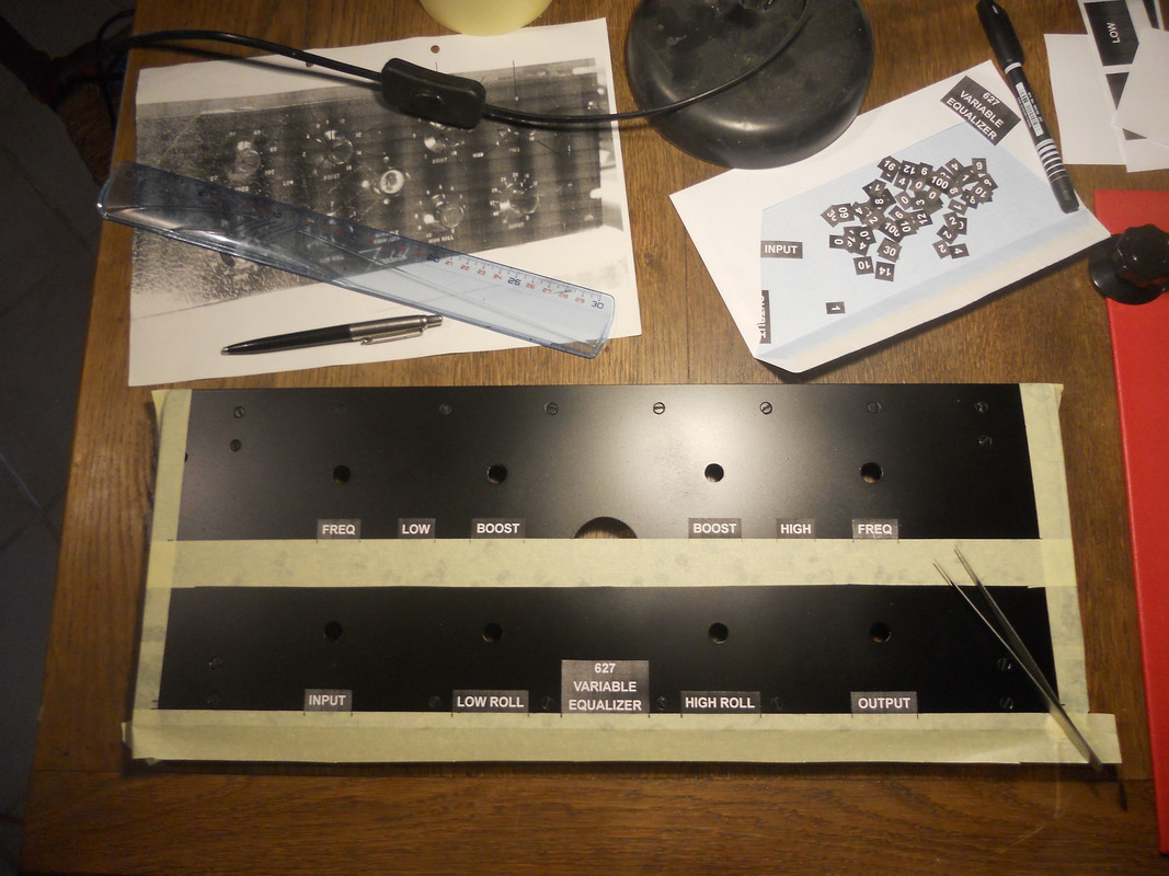
The lettering font is a very close match to Arial and the letters and numbers appear to be about 4mm high.

From the photos I saw, I could not make out if the low roll was showing 60 or 80 before the 100. So I plotted the angle of the letters on the pot against frequency and got a nice curve with 60, but 80 was completely wrong.

The next job is to spray it matte black then to fix the lettering, then the whole lot will be sprayed with varnish.

best
DaveP
 
The front panel after the matte coat.


I had to calculate all the angles for the lettering and I have reproduced them below:-

Low Freq High Freq

20Hz 60o 4k 45o

30 150 5k 120

40 210 6k 180

60 260 8k 260

100 300 10k 315


Low Boost High Boost

0 30o 0 30o

2 85 2 90

4 125 4 130

6 150 6 160

8 170 8 180

10 200 10 215

12 245 12 255

14 290 14 300

16 330 16 330


The High roll is marked at 30o intervals and the low roll is marked to suit your 5-way switch. I have used Ohmite Dials for the input and output.


The lettering was positioned using masking tape and the numbers from pre-drawn discs of paper.

I have attached the lettering as two pdf's if anyone is interested.

Finished front panel


It would have been nice to finish it in the original black crackle finish, it was available to buy in the 1960’s but I seem to remember that some of the chemicals in it were carcinogenic and so it was withdrawn.

Best

DaveP
 

Attachments

  • 627 printing numbers.pdf
    82.2 KB
  • 627 printing.pdf
    82.4 KB
Stove topping Crackle finish is something you can do in a domestic oven. Not sure where I came across it possibly Radio Constructer or on of the other older magazines or on line. I have seen it, its an application of the base material and then a crackle finish which I am sure you knew already.
 
I'm sure your right, but if the paint didn't kill me, then my partner would for using her oven!
 
Looking great.... I've been pretty impressed with some matte (or universal flat it might be called) clear spray as well for extra protection on a couple of things. The finish has been very consistent and seals over thin labeling nicely too.
 
The front panel was finished and pots fitted.


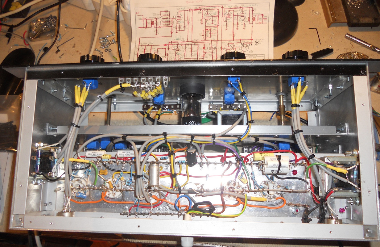
The wiring is now finished and tidied up.


If anyone wants to copy the way I’ve recreated the 3 ganged pots, then I would advise them to get all the brass machining done on a lathe, because mechanical accuracy is essential to get everything lined up with the front panel.


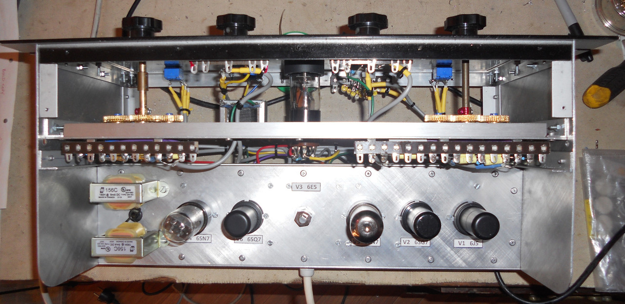
I labeled all the tube bases to help future restorers!

The next task is test that all the voltages are still OK and that I’ve not made any silly mistakes! If there are no errors I will begin setting up and adding the “Select” resistors if required.

Best

DaveP
 
Thanks for the support everyone.

Everything was connected and turned on for test.

There were two problems at the start.

Firstly the high boost caused oscillation, but this was quickly solved by reversing the phase of the 600 ohm winding on T2. It was giving positive feedback instead of negative.

Secondly I found that the boost controls worked in reverse, again this was solved by reversing the wires to the pots.

The next thing I needed to know, in the absence of a manual, was the correct operating level. V1 has a dc voltage of 2.7V so the maximum swing is 5.4Vp-p this is equivalent to 1.9Vrms max input. The IPT has a ratio of 1:5 so this means we cannot put more than 380mV into the 600ohm winding. This is the headroom of course so the normal operating level will be less than this.

I measured the gain of each stage as follows:

V1 gain=15.1

V4a gain closed =3.49

V4b gain closed =5.38

V5a gain closed =5.52

V5b gain =0.668 (cathode follower)

T2 reduction =5.325

T3 reduction =6.63

I will check the curves next but it may take some time.

Best

DaveP
 
During testing, I found that the output stage starts to roll off at 14kHz, I'm not sure why this is at the moment, maybe some Miller effect?
It can be cured by adding about 3nF across the 2.4k cathode resistor of V4a.

The OPT is returned to the B+ rather than earth, I'm not sure what the benefit is, maybe someone can enlighten us?

Testing continues.#

Best
DaveP
 
The setting-up

The Fairchild magazine article on the 627, (Audio Engineering March 1951) says that the resistors for the high and low boost pots are selected to give +16dB boost.

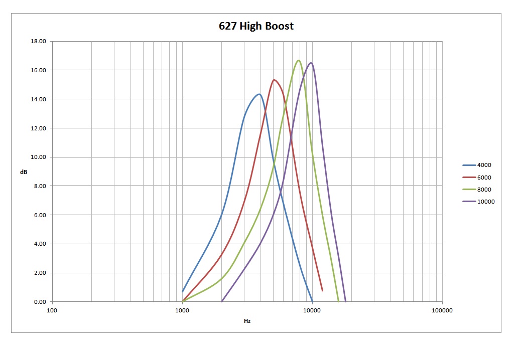
As built, with just the 130 ohm resistors, the maximum boost was +12dB. On this 627, the low boost resistor needed a parallel 82 ohm resistor to get +16dB. The high boost 130 ohm had to be shorted out to get +16dB and a 10k resistor also placed in parallel with the two 3.3k cathode resistors. This latter change increases the current through V5a, but it does not increase the peak boost, it reduces the minimum boost so that the increase equals +16dB.

Without these adjustments it is not possible to obtain the flat frequency response described in Figure 7.

Best
DaveP
 
During testing, I found that the output stage starts to roll off at 14kHz, I'm not sure why this is at the moment, maybe some Miller effect?
It can be cured by adding about 3nF across the 2.4k cathode resistor of V4a.
Did you test the V4 output stage independently, injecting a signal at C10? I don't see why that stage would roll off the high end but I would guess it has to do with the inductor. How did you end up wiring the two L1 inductors? To make the equivalent of a single inductor, you'd want them wired the same way in series, so the positive flux vector is going the same way for both. (not hum bucking). I'm not sure how you would know how the leads are connected to the winding direction though. There is the CA-18-VTB2379 - Choke: 500H, 5mA, if you want to try a different one, (which Colin uses for the AML kit).

You could try swapping a power resistor for L1 and check the frequency response to see if it is the inductor(s).
Also, once the output stage was flat, was the whole audio path flat with the boost section detached from R8? I'm wondering if you are making adjustments to compensate for multiple issues. The original may have had components selected to compensate as well, i.e. for transformers, inductor etc. and with different iron you may have a quite different situation.

Maybe Colin (@Slenderchap) can comment since he has a real one... particularly if the real one does +16dB and the spec'd resistors
If there is anything else you need to know... I have a real one.

Colin

The OPT is returned to the B+ rather than earth
Only guessing, but they possibly tried it both ways and found the noise was lower? I think it could be tried both ways, but you need to reverse the polarity of C22 if you try it to ground. There will not be a DC voltage drop across T3 but there will be a drop across L1 and the cap has to be oriented correctly for the potential difference. Or maybe they could use a lower rated cap for C22 with it returned to B+.
 
I ve seen in the AML EZ627 Version schematic that C17 470nF = Fairchild 627 C22 0.5uF before the Output TX can be optionally increased by adding a 220nF (C18) parallel to 700nF achieving a flat frequency response. Does this make sense, asked as non expert?🤔
 

Attachments

  • Screenshot_20221220-215241.png
    Screenshot_20221220-215241.png
    275 KB
Last edited:
I did test the output stage separately by putting a signal on C10, that's how I discovered it. I also thought of cancelation from the two chokes facing each other or wired humbucking, I will sort this as a separate issue. The caps feeding the OPT are 630V Polyprop so they don't need reversing if the OPT is wired to earth. Normally, the caps feeding the OPT give a very low resonance with the OPT if they have too much capacitance, I have never seen them affect the top end before.

At the moment I am making adjustments to the high end boost components because the values shown in the original boost circuit are not calculated to give 10kHz, but 14kHz (2.2k with 5nF when the pot is on zero)

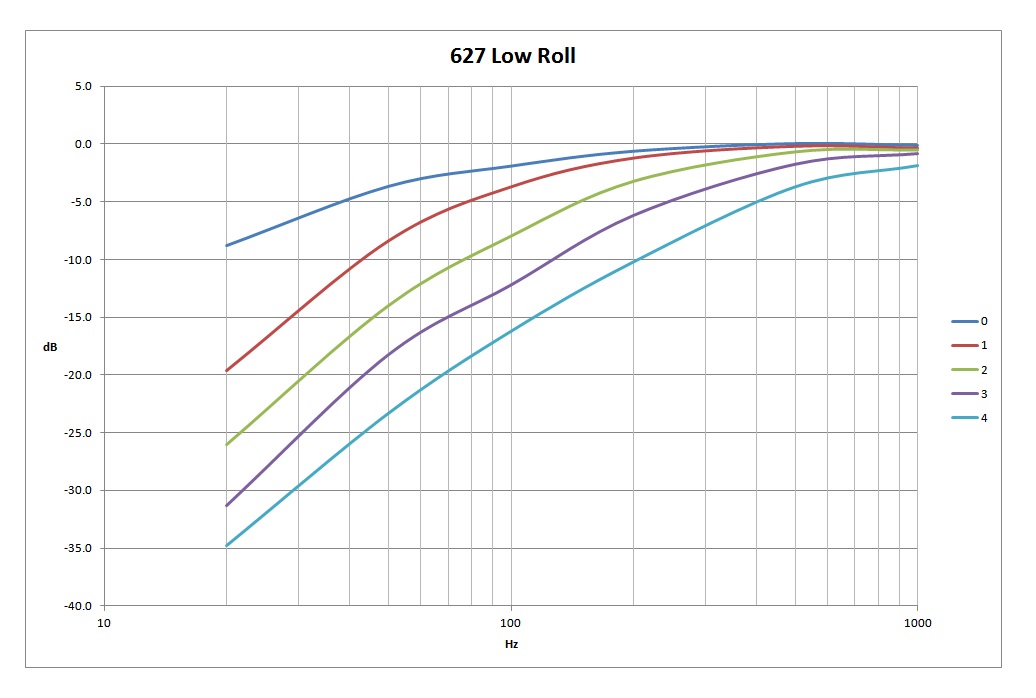
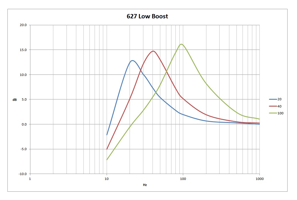
This is the low roll performance as measured with the switch in the positions listed in the schematic.


This is the low boost as built.


Thanks to everyone for helping with suggestions and support, I wish you all a happy Christmas

Best
DaveP
 
Hi Dave, thanks for all your efforts! A lot of new knowledge, fantastic. I think for the Hi Boost a 6N8 Filmcap with the 2.2Kohm + a variable 5K pot gang from the tripple Pot should give the desired frequency range from 10K down to about 3K cycles. I think that means the two other gangs of the HF Boost Frequency tripple pot should have 10K Ohm.
 
As I mentioned earlier, there is an unexpected problem with the frequency response of the output stage. I injected the signal at C10 and on the Attached chart; the original circuit is in Blue.

I decided to check whether the series connection of two chokes was having a detrimental effect on the frequency response. I shorted out one choke and this is shown with the Red trace. Surprisingly, the low end response was better and so I left it like that. In fact the Hammond 156C is rated at 150H at 8mA, so my guess is that at half this current in the 627, it has a higher inductance, so two chokes are not necessary.

The Audio Maintenance schematic (earlier in the thread EZ627 Colourbook), adds a 0.22uF cap to the standard 0.5uF output cap. This value depends on the OPT so it’s normal to tune the low end response with this cap. This is shown in green on the chart but it’s also under the Purple trace which shows that the low end is now flat to 20Hz.

I decided to short out some of the top end negative feedback with a 4.4nF cap across the cathode resistor R14, this mod extends the frequency response to 10kHz. It does not seem worth going further because the equalizer is designed to extend the response with the existing controls.

Best

DaveP
 

Attachments

  • Output Stage.jpg
    Output Stage.jpg
    96.4 KB

Latest posts

Back
Top