dissonantstring
Well-known member
hi mikerisha,
you are doing well with your research.
looks like your diagram is pretty spot on if you are in 110/120V land. where are you located (you should put it in your profile so people have a reference).
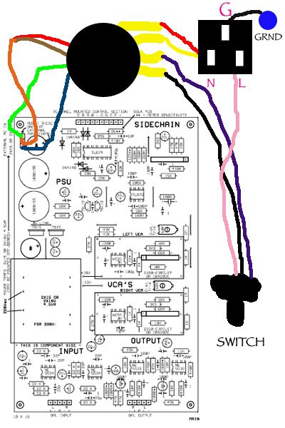
the diagram solderspongebob posted is for 220/240V (if you had not noticed), but the diagram you posted has the correct primary connection for 110/120V mains.
Primaries hook-up note:
looks correct, just the switch not shown. if you're switching the live, then run the BLK/VIOLET (tied together) to the switch and a wire back to the LIVE tab on the inlet. The RED/YLW is correct (tied together and soldered to the NEUTRAL tab). EARTH tab on inlet to chassis as you drew correctly.
Secondaries:
looks correct as well. the RED/BRN tied are your 0V center tap (CT). the BLUE and the GREEN secondary wires are carrying your AC (around 15VAC each).
the only thing i see which may be a problem is that jakob intended the off-board transformer connections to be hooked-up at the top left corner of your drawing. AC-0V-AC connection point. component placement of the bridge rectifier changes with either on or off-board transformer.
also, your CT needs to be connected to the PCB (your drawing doesn't show this). the CT is your 0V. you're almost there...very, very close. if not you'll have the same issues as casio and you will not be able to reference DCV correctly.
regards,
grant
you are doing well with your research.
looks like your diagram is pretty spot on if you are in 110/120V land. where are you located (you should put it in your profile so people have a reference).
the diagram solderspongebob posted is for 220/240V (if you had not noticed), but the diagram you posted has the correct primary connection for 110/120V mains.
Primaries hook-up note:
looks correct, just the switch not shown. if you're switching the live, then run the BLK/VIOLET (tied together) to the switch and a wire back to the LIVE tab on the inlet. The RED/YLW is correct (tied together and soldered to the NEUTRAL tab). EARTH tab on inlet to chassis as you drew correctly.
Secondaries:
looks correct as well. the RED/BRN tied are your 0V center tap (CT). the BLUE and the GREEN secondary wires are carrying your AC (around 15VAC each).
the only thing i see which may be a problem is that jakob intended the off-board transformer connections to be hooked-up at the top left corner of your drawing. AC-0V-AC connection point. component placement of the bridge rectifier changes with either on or off-board transformer.
also, your CT needs to be connected to the PCB (your drawing doesn't show this). the CT is your 0V. you're almost there...very, very close. if not you'll have the same issues as casio and you will not be able to reference DCV correctly.
regards,
grant