GSSL HELP THREAD!!!

GroupDIY Audio Forum

Help Support GroupDIY Audio Forum:

This site may earn a commission from merchant affiliate links, including eBay, Amazon, and others.
Sorry, I will try to think better next time  :p
(I am out of ideas for your wrong voltages on transformer secondaries)
Hope you will get it solved soon, good luck!
 
looks like an iluminated double pole single throw switch, the plastic bar in the middle separating hot and neutral.
Connect center pole on left side to hot of your iec-connector, bottom pole left side connecting to 1st transformer primary wire.
Connect center pole on right side to neutral of your iec-connector, bottom pole right side connecting to remaining wire of transformer primary.
If so (could be wrong), this also will fix your voltage readings with your current limiting lamp inside the switch wierd in series.
 
hi Harpo

tanks for the good tip, but i put this switch in the garbage  :)

i friend told to use another, i try a toogle switch and this are ok, i measure now 17.7v

did you think is to much to the gssl???

tank you
 
ribazigi said:
i measure now 17.7v
You measured the secondary AC voltages of your transformer without load. This will drop to about 15-16VAC with load (the gssl) connected, may vary depending on your local line voltage.
 
Hi All!

Any Clues on!

All is done without sound going thru the unit!

When I put the ratio at 2:1, i've got 2.68mA, the meter is going to max and there's the biggest limitation i've ever seen!

When I put the ratio at 4:1, i've got 0.70mA and the meter is staying a half and I have a big compression!

When I put the ratio at 10:1, i've got meter to zero and compression is working nicely!

So is there is one of you who already got this problem, help me, please.

Voltage with ratio on Pin 8 of the TL074 is going form -5.5V to -1.3V and to 0.

I have to much current in my sidechain!

I'm reading all the post of this thread but no kind of this problem!

 
hi,

sorry for not replying any more on your problem, i was busy and didn´t have the chance any more...
but as i see you got the prob. sorted out!

good luck,
mark


ribazigi said:
hi Harpo

tanks for the good tip, but i put this switch in the garbage  :)

i friend told to use another, i try a toogle switch and this are ok, i measure now 17.7v

did you think is to much to the gssl???

tank you
 
hey everyone..
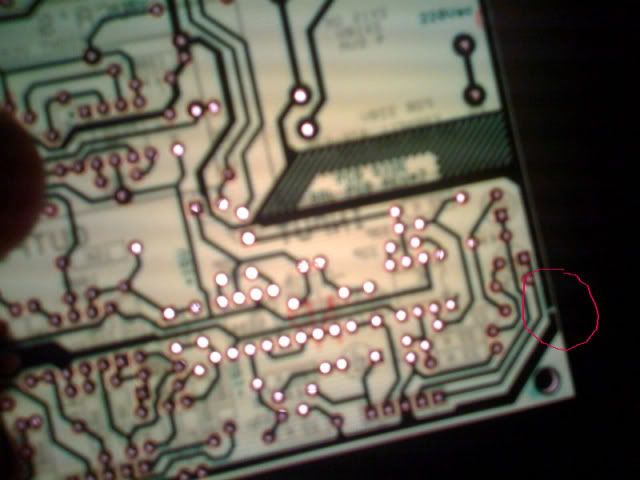
received my PCB last week, and before I started to work on it, I noitced this...  how big of a problem is this?  if im in trouble, could i drill and solder a jumper around it?  please dont tell me im screwed.. i would be bummed.

photo-1.jpg
 
just scrap off some of the solderstop paint away, and solder a bridge, and you should be fine. no need o drill holes... even though drilling holes is fun :)
 
stereokillah said:
mikerisha
it's nothing

on mine i cut all the green part cause there is a ground loop "FOR ME"

So are you saying I should leave it?  any senior members have any advice?

Also, Im bloggin all my work..
if anyone is interested in seeing the progress of a complete rookie trying to make it happen, check out:

www.mikerisha.com/gssl
 
mikerisha said:
So are you saying I should leave it?  any senior members have any advice?

I'm not a senior, but I didn't cut any ground traces, or anything else on the PCB, but I used an external -15/+15 PSU. Noise is below -104dB, although rises to some -90dB on full gain reduction. "mastering grade"
 
mikerisha said:
Also, Im bloggin all my work..
if anyone is interested in seeing the progress of a complete rookie trying to make it happen, check out:

www.mikerisha.com/gssl

- Judging from the images, you probably got two of your rotary switches wrong. You need pcb-pin types (because they go into the "control" PCB), but two of them look like wireing-pin types. Nothing that can't be fixed with a sharp cutter though..

As for the topic on ground loops, the PCB by itself is virtually noiseless despite of the clear-to-see loops. The most common ground-related-noise error is if you use metal bolts&spacers for mounting into your chassis, you risk of cross-connecting some grounds that don't like to see each other (because ground on the PCB goes out close to the mounting holes). Use isolating washers to avoid this.

Jakob E.
 
Hey guys,

still working on that hum of mine. I found out (after using the following method):

gyraf said:
You could maybe check for hum on the power lines with a 1uF polyester capacitor in series with a cable going to an amplifier, and a 10K resistor shorting from after the capacitor to ground. The capacitor lets AC through, but blocks the DC voltage.

Connect amplifier input ground to your device-under-test's 0V, and use the free end of the capacitor as a probe.

Remember to keep amplifier volume down, as there will be a VERY loud click when you attatch/detatch the "probe".

And don't use an expensive amplifier/speaker for this - there still is a real possibility that it can be damaged.

Maybe a cheap computer-type powered speaker would be a good tool for this?

A setup like that could also be used to trace signals through a circuit - making it much easier to trace errors.

Jakob E.

...that my power rails are humming. I know there's a very easy solution to this with something like a CRC or RCR chain, but I can't really remember how to do that... Could anyone please help me out with a short description of how and especially WHERE to direct my AC out of my power rails?
I use a 50VA toroid, my +/-12V and +/-15V rails are ok, nearly perfect...

Thanks!

PS: Now this freaks me out: I just wanted to measure the AC on the toroids secondaries and I can't measure any voltage at all??? Am I completely stupid or why could that be? I mean, the unit is running and doing its job great, but there's alway a hum on it...
 
gyraf said:
mikerisha said:
Also, Im bloggin all my work..
if anyone is interested in seeing the progress of a complete rookie trying to make it happen, check out:

www.mikerisha.com/gssl

- Judging from the images, you probably got two of your rotary switches wrong. You need pcb-pin types (because they go into the "control" PCB), but two of them look like wireing-pin types. Nothing that can't be fixed with a sharp cutter though..


Jakob E.


Hey jakob.. I got three that are pin type, and two that are looped like that for the two switches that dont go into the control pcb..

thats ok right?
i ordered everything of Greg's parts list .pdf
 
osterchrisi said:
PS: Now this freaks me out: I just wanted to measure the AC on the toroids secondaries and I can't measure any voltage at all??? Am I completely stupid or why could that be? I mean, the unit is running and doing its job great, but there's alway a hum on it...

@ osterchrisi,
are you using your meter in AC mode with the two probes measuring across the secondary lines of the transformer (i.e. one probe on one AC leg/wire and the other probe on the other AC leg/wire)?  you should get the correct AC voltage measuring across the secondaries and about half VAC if you measure one side with reference to the CT. 

@mikerisha,
you should be fine if you have PCB pin type rotary switches for the ratio, attack and release (which will be mounted to the front panel control PCB) and you would be correct if you are saying that the two rotary switches with the solder tabs (looped as you call them) are for the bypass and the power.  remember that the power switch should be able to handle at some current as the inrush current upon turn on could be substantial.  mouser now carries the lorlin power type rotaries which can be used safely to switch AC mains.

regards,
grant


dissonantstring said:
osterchrisi said:
PS: Now this freaks me out: I just wanted to measure the AC on the toroids secondaries and I can't measure any voltage at all??? Am I completely stupid or why could that be? I mean, the unit is running and doing its job great, but there's alway a hum on it...

@ osterchrisi,
are you using your meter in AC mode with the two probes measuring across the secondary lines of the transformer (i.e. one probe on one AC leg/wire and the other probe on the other AC leg/wire)?  you should get the correct AC voltage measuring across the secondaries and about half VAC if you measure one side with reference to the CT. 

Yes, sure I do. Thanks anyway. I mean, I have the right voltage (~32VA) at the bridge rectifier. Maybe I just don't remember I aplied some insulating coat over these secondary wires (I just measured on the board surface) ...  ::)
 
hi mikerisha,
any 50K LIN pot will do.  for cheap go with Alpha (Mouser: 31VA405-F) or for better feel and construction the rather expensive PEC type (Digikey: RV4N503C-ND) both are carbon type which i'm pretty sure will get "scratchy" at some point due to DC on the pots when used for the threshold control, but they should work fine for the make-up gain (and the threshold for that matter - i used the cheap Alpha pots and have not had problems yet).
even better would be to use the conductive plastic type which can handle the DC.
many options to choose from.  just make sure they are solder lug connections and have the proper shaft diameter and length for your knobs/purposes.
regards,
grant

p.s.  i can't be sure as i've not used them, but i think the CTS pots greg listed on his BOM are PCB mount type with pin connections rather than solder lugs.  best to check the datasheet to be sure.

edit: gave mikerisha some bad info with wrong PEC Digikey part number.  part number corrected, but ALWAYS double check with datasheets online to verify part.  i'm not responsible for my actions as i'm usually wrong.  ;)

 
Back
Top