GSSL HELP THREAD!!!

GroupDIY Audio Forum

Help Support GroupDIY Audio Forum:

This site may earn a commission from merchant affiliate links, including eBay, Amazon, and others.
dissonantstring said:
hi mikerisha,
any 50K LIN pot will do.  for cheap go with Alpha (Mouser: 31VA405-F) or for better feel and construction the rather expensive PEC type (Digikey: RV4L503c-ND) both are carbon type which i'm pretty sure will get "scratchy" at some point due to DC on the pots when used for the threshold control, but they should work fine for the make-up gain (and the threshold for that matter - i used the cheap Alpha pots and have not had problems yet).
even better would be to use the conductive plastic type which can handle the DC.
many options to choose from.  just make sure they are solder lug connections and have the proper shaft diameter and length for your knobs/purposes.
regards,
grant

p.s.  i can't be sure as i've not used them, but i think the CTS pots greg listed on his BOM are PCB mount type with pin connections rather than solder lugs.  best to check the datasheet to be sure.

Thanks grant.. gonna order the parts tomorrow..

Got another question.. When cutting the IC holders for the VCAs, does it matter which is which when i place them and solder them into the PCB?  Im guessing no, may be a stupid question, but I just want to be sure.

Thanks again everyone for being so helpful..

:) :) :) :) :)
 
hi mikerisha,
i'm not sure i understand when you say "IC holders for VCA" i am assuming you mean SIP sockets or in-line sockets.  for the VCA it does not matter the orientation, but please make sure that when you insert the VCA that pin 1 is in the correct orientation (designated by a line after the hole).  i've used break apart SIP sockets and 8-pin SIP sockets, but i don't believe the ones i used had an marker for an orientation.  it doesn't really matter as long as you orient the VCA correctly so that pin 1 goes to the proper pad.

if for some reason i'm not understanding correctly ;D and you are refrering to the IC DIP sockets (8-pin) then the side with the U-shaped cut in the center should go the same was as the overlay outline illustrates on the PCB (but you probably know that already).
hope this makes sense.
regards,
grant
 
once again, Grant.. thanks dude..

sorry my terminology isnt always on point.  ;D  Im working on it, as I learn more and more every minute.  I cut the inline sockets this morning, and will solder them in later. 

(more questions to come...)
 
One of my finshed GSSL's is housed in Purushas nice custom made case with the bypass & power LED indicator 8mm cut outs so I'm assuming that I can tap the "Power On LED" supply from before the 1K resistor & run the + positive Bypass LED from that in parallel (adding a 1K resistor for the bypass LED as well?) 

So it's OK to join the return - negative from the Power On / Bypass LED's as per normal on the control PCB I assume? Are there any potential problems running 2 LED indicators from this connection? I've a 30VA 18V Toroidal transformer installed.

Any advice welcome ;D


trancedental said:
One of my finshed GSSL's is housed in Purushas nice custom made case with the bypass & power LED indicator 8mm cut outs so I'm assuming that I can tap the "Power On LED" supply from before the 1K resistor & run the + positive Bypass LED from that in parallel (adding a 1K resistor for the bypass LED as well?) 

So it's OK to join the return - negative from the Power On / Bypass LED's as per normal on the control PCB I assume? Are there any potential problems running 2 LED indicators from this connection? I've a 30VA 18V Toroidal transformer installed.

Any advice welcome ;D
Better take it from the +15V with - depending on wanted LED-briteness - maybe 1K5 resistor in series with the additional bypass LED. The 78L12 will hardly deliver this additional 10mA current without disturbing the sidechain VCA.
Just my 2ct.
 
Thanks Hapro, I've tapped the 15+ / 15- from near the VCA's on the main board & the bypass LED is  now working fine wired up through a 3DPT switch for bypass along with compression off / on & makeup gain off ;D

Cheers JK
 
hey y'all..

Im gonna be straight up.. when it comes to hooking up the juice to this project, I honestly have no idea what to do...  I have been learning and learning.. and I pretty much have my head around populating the board.  It took a few weeks of research, and thankfully I have plenty of soldering skills making cables and patchbays.  I understand signal flow enough to get by, but I feel really sketchy about hooking up the tranny.

Is it possible to get that info through a thread? Or would it be safer finding someone around me to help me out?

If someone wants to help me out, that would be awesome.. if not, well its ok, ill find someone to come by and let me know what to do.. but just in case someone wants to help me out.. here is what i have..

Amveco Magnetics 62063 Transformer

Wires avail:
BLUE
RED
GREEN
BROWN

Then from the Yellow Wire group:
BLACK
PURPLE
ORANGE
YELLOW

Just tell me what to solder where, and Ill give it a shot.  If anyone can draw a diagram off the pcb sheet, that would be freakin rad.  But like I said, if not, I will do my best to find someone to help me out.. Thanks for your time and your on going help.  :D
 
Hello all,

I've gotten myself into a rather elaborate first-time DIY project (building a "mastering console" w/ two W492 EQ's, GSSL, and Lawo summing section). I just finished putting together the GSSL and am having the following problem:

Two points on the board are metering as double what their voltages should be. I'm getting a touch over -25v at the -12v point, and +30v at the outermost +15v point (that is, not the point which uses jumpers on the component side of the board, but the one closest to the outer edge).

Any thoughts on what could be causing those double voltages? I didn't have any of the ICs or THATs in when I first powered it up, as I was afraid of blowing them out (which I'm guessing I would have with this problem?). The other 4 points meter as they should...

My apologies if this has already been covered somewhere in the thread. 157 pages is a lot to sift through at 3am, and I didn't have any luck with keyword searches.   
 
hi mikerisha,
i don't want to sound cranky - i'd rather be helpful, but please do a search prior to asking questions. 

it is sort of the rule of thumb around here to search prior to asking questions as many, many, many (did i say many ;D) questions have already been answered already.  most problems with builds are often common problems many encounter so searching will most likely give you the answer.  too many questions without searching (out of laziness or whatever) especially from inexperienced or new members, often ends up with the other more experienced members not willing to help. i understand that it can be stressful thinking you'll be doing something which may damage your build, but that's how we learn.  it's those who come through it with all the frustration that comes with it that makes them better builders of DIY.  believe me, i've been there and this forum has been so helpful and generous over the past 4-1/2 years of my DIY experience and allowed me to build so much equipment (some 20 pieces of gear now and still growing).

another rule of thumb - help those who help themselves.  you'll learn more trying to find out how to solve problems by yourself.  no problems with asking, "if i do this or i'm thinking of doing this, will this be o.k.?", but only after searching and not being able to find your answer.

rant off. ;)

anyway, i did a search for you to show you how fruitful it can be:
http://www.groupdiy.com/index.php?topic=29340.0
especially look at the link to the DIY Factory page with Mark Burnley's awesome transformer hook up diagrams.  very educational for a newbie and i keep a copy in my files for reference to this day.

if you have any questions after reading all the information, then i'd be more than happy to help clarify things for you.
with respect and regards,
grant
 
hi casio,
how are you measuring those voltages?  DC reference to where?
are your XLR connectors' pin 1s connected to the PCB at the 0V points?

i would avoid inserting your ICs and VCAs into the board until you work this voltage problem out.


Cheers, Grant..

I should know better.. I sometimes forget how massive this board is.. But I promise you, I have read almost 80 pages of this thread, just doing research.. BUT, i should have used the search option. 

I guess it just means Im not doing enough research..  :p

Thanks for the links and I will continue to expand my brain.
 
mikerisha said:
I guess it just means Im not doing enough research..  :p
Thanks for the links and I will continue to expand my brain.
no problem mike.  good on you.
hope this helps with your learning.  i, myself am still learning everyday by reading  on this great forum and else where.  just be patient and if any question on anything comes into your head, do a search (and don't just relate it to lab, google it as there is so much info out there).  there's great satisfaction when you can "do-it-yourself"  ;)

please be safe when working with mains voltages.  as mentioned, better to ask..."i plan on doing this...is it o.k.?"  those types of questions will be answered i'm sure, but "can you please just tell me how to do it" don't cut the mustard around here since at least half of this forum is about learning so eventually you'll be able to go further than just painting by numbers DIY.

oh, please remember to always connect your AC mains inlet to chassis ground before moving forward with any power up.
all the best,
grant
 
dissonantstring said:
hi casio,
how are you measuring those voltages?  DC reference to where?
are your XLR connectors' pin 1s connected to the PCB at the 0V points?

i would avoid inserting your ICs and VCAs into the board until you work this voltage problem out.

Thanks for the reply dissonantstring,

I was measuring my voltages with the ground of my multimeter on the metal tab of one of the voltage regulators. When I tested it, the only things connected to the main board were the full control panel/pots and the PSU. No inputs or outputs were connected, nor did i connect anything to earth/ground (not an ideal test, I suppose). What's the best way to go about testing things/trouble shooting? Since I'm metering correct voltages at some points (assuming I had used a proper method), I'd image it's something inline/past the main power section. I'm by no means an expert on that side of things, let alone an intermediate!


_casio said:
I was measuring my voltages with the ground of my multimeter on the metal tab of one of the voltage regulators.
Not the best idea for a 0V reference. In this circuit the 7815 has 0V on the heatsink surface (might be different in other circuits), the negative 7915 regulator has negative raw DC voltage connected to its center pin, internaly connected to this metal tab (the one you took as reference). The link/wire between 7915 regulator and the 1000uF cap or the transformers center tap will give an easy to reach access to the 0V reference.
 
Harpo said:
_casio said:
I was measuring my voltages with the ground of my multimeter on the metal tab of one of the voltage regulators.
Not the best idea for a 0V reference. In this circuit the 7815 has 0V on the heatsink surface (might be different in other circuits), the negative 7915 regulator has negative raw DC voltage connected to its center pin, internaly connected to this metal tab (the one you took as reference). The link/wire between 7915 regulator and the 1000uF cap or the transformers center tap will give an easy to reach access to the 0V reference.

Thank you for the tip. I re-metered with the center tap of the transformer as reference, and still the same result...
 
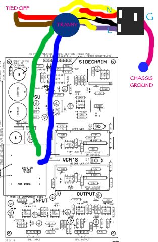
so after doing some research on hooking up the juice..

here is my first "guess" as to how to hook it up, after reading a few diagrams, and seeing some completed projects..

pcb.jpg


can anyone tell me how far off i am?  i got this idea from a thread that was suggested to me to look at.

do the tied off ones go to the power switch?

PLEASE PLEASE PLEASE excuse my noob-ness.  I have a feeling I am somewhat wrong, because of what goes to the power switch...

 
Hiya mikerisha,

I've hashed together a mash-up of the schematic from Jacob's construction PDF (credit to Jacob) and the diagram from the Amveco site:

SSL PSU.gif


This should get you going, but I recommend you ensure that you have no IC's (op-amps and VCAs) in their sockets when you power up for the first time, just in case!

Once powered up, check the voltages on the IC sockets to ensure the regulators are doing their job correctly (you'll find it much easier to check the sockets than to try and hold the meter probes on the legs of the voltage regulators, plus if you slipped with the probe on the regulators, you might short two legs together!).

Hope that helps!
 
_casio said:
Thank you for the tip. I re-metered with the center tap of the transformer as reference, and still the same result...
I'm getting a touch over -25v at the -12v point, and +30v at the outermost +15v point (that is, not the point which uses jumpers on the component side of the board, but the one closest to the outer edge).
Any thoughts on what could be causing those double voltages? I didn't have any of the ICs or THATs in when I first powered it up, as I was afraid of blowing them out (which I'm guessing I would have with this problem?). The other 4 points meter as they should...
Where-/whatever the outermost +15V or the other 4 points are, you might have measured raw DC voltages (before regulator).
Check voltages on IC sockets with multimeter set to VDC and its common terminal connected to a 0V reference on pcb.
NE5534 sockets should measure +15VDC @ pin7, -15VDC @ pin4
NE5532 sockets should measure +15VDC @ pin8, -15VDC @ pin4
TL074 socket should measure +12VDC @ pin4, -12VDC @ pin11
TL072 socket should measure +12VDC @ pin8, -12VDC @ pin4
Measured voltages may vary by +/-5%, depending on type/manufacturer of regulator.
-Harpo
 
hello, my first GSSL is finished but i've got problems:

little noise at full compress

and some distorsion when gain is at full with small attack

i used this vca:

http://fr.farnell.com/jsp/search/productdetail.jsp?SKU=1354172

see you later!!!!
 
Back
Top