GSSL HELP THREAD!!!

GroupDIY Audio Forum

Help Support GroupDIY Audio Forum:

This site may earn a commission from merchant affiliate links, including eBay, Amazon, and others.
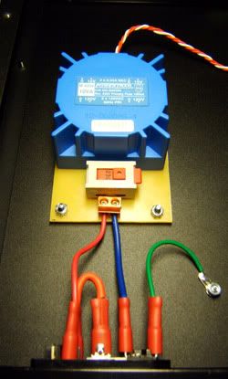
Jakob, I tried to look for information on hooking up up the transformer but no luck. Maybe I am overseeing something. I am using a toroidal transformer but don't know which color cables go where on the PCB. Any links to threads would be greatly appreciated.

Adam
 
the colors depend on the transformer you have. Look on page 4 of the ssl help thread. The colors listed on there are for the amveco (I believe) which is what is in greg's part list. A lot of us have been using avel lindberg because the amveco was on back order.

I copied greg's post and attempted to translate the colors for the avel lindberg, and here's what I came up with. I could be wrong though---hopefully someone can double check this???


On the primaries:
Tie BLUE and VIOLET together and that goes to your common on jack it's "N"(not GND).
Tie GREY and BROWN and that goes to the hot (on jack, "L") (115VAC/120VAC).

On the secondaries:
Tie RED and ORANGE together...
Then measure between BLACK and YELLOW and you should have approximately 30VAC.

When you go to connect to the Main PCB, the RED/ORANGE (which are connected together), go to the middle point of the three. Connect Black to the outside and Yellow to the one on the inner part of the board.

Basically we're connecting the primaries is parallel and the secondaries in series.
 
I am using Kev's parts list and I have a transfo from Jaycar and it has 6 wires. I need to know where to solder them on the PCB and in which color sequence. Here is what the label reads:

IP: 0-240V 50hz ORG-ORG
OP: 0-15V (0.67A) 0-15V(0.67A)
YEL-RED WHT-PUR


I am confused with "IP" and "OP" (however, I'm down 'wit OPP)

Any help is appreciated,

Adam
:sam: (This represents Newcastle for me)
 
I am using Kev's parts list and I have a transfo from Jaycar and it has 6 wires...
IP: 0-240V 50hz ORG-ORG
:sam: (This represents Newcastle for me)
You will probably have to hook it up to your clothes dryer outlet in Alabama - it's 240V only primary for most of Jaycar's toroid line. Many other toroidal power transformers (sold outside Australia) have dual primaries so you can wire them for 120V or 240V, but not from Jaycar aside from the encapsulated ones. For everything after the primary, Mark Burnley's wiring guide might help you: http://www.diyfactory.com/data/transformer_connections.gif

I'm a big fan of Newcastle Brown Ale too. So down a few pints and then give Jaycar a call and ask them why they would sell a 240V transformer to someone in the USA...:evil:

BTW the Jaycar encapsulated toroids don't come with suitable secondary voltages for the GSSL compressor. But over here Altronics has one that will work. I used it in my GSSL and made a little PCB with a switch so it can be used with either 120 or 240V:
ssl_ps.jpg
 
So let me get this straight...Input power (IP) are your primary wires that recieves power from a 110v source (here in the States) which is wired to the IEC inlet, and Output power (OP) are the secondary wires from the transformer to the PCB (+-15v). Well I'll be a sum'bitch! :shock:

:sam: :sam: :sam: :sam: :sam: :sam: :sam: :sam:
 
Has anyone tried a standard transformer in this unit instead of a toroid? I have a few (1A) 14-0-14 transformer lying around. They appear to fit in a 1 U chassis. They look simular to the ones in UREI LA4a, or any of thier EQs.

I am assuming at 1A per secondary, it will have enough current to maintain the 15 v after the diodes/regulator ect. Am I right? I think PPR said that the diodes create a multiplier of 1.4 of the input voltage.

Joe
 
So I finally got around to firing up my ssl. I flipped the switch and nothing happened. I checked the fuse and it was done. I put another one in and I saw the led (meter led that was added) light up and quickly go out. I don't think the normal control pcb led ever lit up. That fuse is now done as well.

meter led: I wasn't sure how to install that and I was a little shakey on the toroid, so I took it to my tech to do those 2 parts. He used what I assume is the appropriate restistor?

Any idea where I should start?

:sad:

I'm using .315 amp 250 volt gma fast acting fuses.

Edit: I was going to try taking out the extra led, which is attached to one of the regulators. I noticed that I missed a jumper right by the regulators. I added that, replaced the fuse and powered it up. It turned on and the meter led lit, and stayed on, the control led didn't. After a minute, I turned it off and then tried to turn it on again and now it won't do anything anymore. Do I need slo blow fuses or is it something else I screwed up?
 
thanks jakob. I found upon another problem while I was trying to search other things I'd missed.

78l12 and 79l12 were switched! :oops:

I'm so mad at myself, I remember being extra careful with that (or so I thought)

If the fuse was burning because of the power up, do you think everything else is safe? I'm going to put in new 78l12/79l12's just to be sure.
 
Joy-of-joys ---> plugged in the first of 2 SSL clones last night and all seems to be working spot-on straight off.!.

Wouldn't have been possible without all the aces-of-info around here.

Mighty thanks to Mr.Gyraf and all you others!

...

...

will try to finish the 2nd one off asap -- the 2nd will have proper 202 VCAs while the 1st has simple THAT2180s - will be interesting to compare them.
 
I copied greg's post and attempted to translate the colors for the avel lindberg, and here's what I came up with. I could be wrong though---hopefully someone can double check this???


On the primaries:
Tie BLUE and VIOLET together and that goes to your common on jack it's "N"(not GND).
Tie GREY and BROWN and that goes to the hot (on jack, "L") (115VAC/120VAC).

On the secondaries:
Tie RED and ORANGE together...
Then measure between BLACK and YELLOW and you should have approximately 30VAC.

When you go to connect to the Main PCB, the RED/ORANGE (which are connected together), go to the middle point of the three. Connect Black to the outside and Yellow to the one on the inner part of the board.

Basically we're connecting the primaries is parallel and the secondaries in series.

Okay, so I got an Avel Lindberg from Parts Express. I am about to wire it up and hopefully someone can back me up on this.

TIE TOGETHER:
Blue - 2x115v
Violet

TIE TOGETHER:
Gray - 2x115v
Brown

TIE TOGETHER:
Red - 15v
Orange - 0v

Black - 0v - To solder joint nearest corner of PCB
Yellow - 15v - To opposite solder joint nearest components
Red/Orange - To middle
 
All right.. my turn now..
I noticed the thread on 2181 mods but not on 2180 mods, so I thought I should ask some questions.

I just finished putting together another clone and this time I used 2180LA for main VCAs and 2181LB on the SC.

After looking at this design note from THAT
www.braudio.com/forumfiles/2180modref.pdf
I only saw a few things I should leave out of the emulation circuit.
I've circled them on this pdf.
www.braudio.com/forumfiles/2180mod1.pdf

Could anyone check and see if this is all I need to do? I looks like it for me, but I could be overlooking something.

I powered the unit up without those components and I get nothing. (audio)
I also noticed the 5534 on the emulation section got really warm, and the voltage reading on pin 4 was something like 6V. Which I thought was kind of strange.

Any ideas??

Thanks
Gil
 
Hi Gil,

I believe that we've covered most of those questions in this thread already?

btw, I've updated the ssl-page at gyraf/diy to cover 2180/2181 in simple terms.

Jakob E.
 
Hello everyone.
I have a couple of stuffed SSL boards, minus the VCA's, until i am clear on everything.
I checked the power rails, and +15 is dead on, +12, and -12 are on as well. -15 is reading at -16.45 though. Both units are getting almost exactly the same readings on all including the "high" negative
I did some brwosing through the forums and found some info on power supplies where some folks were saying that the 79 series regulators could register hot until a proper load was put on them. This sounds like what is going on with my 2 units. I have not soldered in any of the jumpers yet, so the power is not seeing a proper load.
Just checking to see if this jibes with other's knowledge of who these guys work. It would be a bit wierd if both the regulators were off in exactly the same way<G>
Any thoughts?
Ian
 
Back
Top