Guess the transformer?

GroupDIY Audio Forum

Help Support GroupDIY Audio Forum:

This site may earn a commission from merchant affiliate links, including eBay, Amazon, and others.
you are almost there,

try 1000 turns for better linkage and therefore a more accurate test,

keep the voltage across the coil constant as perm changes with level, since perm relates to inductance, changing the level puts you on a different part of the BH curve/iductance so you want voltage constant,

your graph looks right and it will get better if you do the above,

looks like you have a good ammeter for measuring those microamps,


keep up the good work!
 
I am not measuring microamps, I am measuring voltage across the resistor and using the voltage across the resistor divided by the value of the resistor to produce Amps.  Is that ok? (see schematic in pdf)

I will adjust the levels to keep the voltage across the coil constant.

Should I be using an ammeter instead of just dividing RMS Volts by Value of Resistor?

Is the calculation producing Inductance in Henries?  Or permeability?  Because it would seem that the inductance would increase when I doubled the turns, and it doesn't.

I will go to the basement again... and run the numbers with constant voltage across the coil for all frequencies.

 
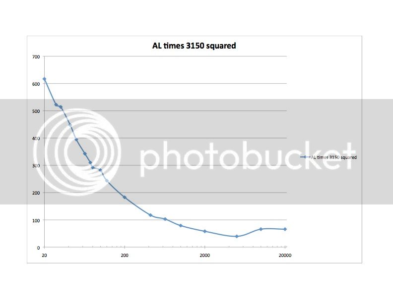
Ok... back from the basement. And I think I figured out what I was doing wrong (I was not using the voltage across the coil in the formula but the voltage across the resistor (doh!)).  Anyway that is fixed now and I am still a bit befuddled.  I am looking for inductance that is equivalent to the inductance that CJ measured on the S-217-D copy, and the values I am getting are too high as can be seen here
al3150sq_zps3f45486a.jpg


Does that mean these are not 50% nickel but something more permeable, or am I doing something wrong.

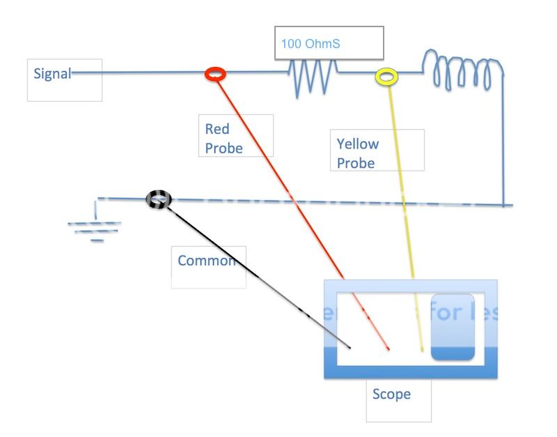
Here is my setup:
schem_zps6c8d2239.jpg


I am using the scope to measure the RMS voltage at the red and yellow probe points.
Then I subtrack the values from those points to get the voltage across the 100 ohm resistor.

So for instance:

At 20 Hz, I get 1.00V RMS at the Yellow Probe, and 1.32V RMS at the Red Probe.  So there is 0.32V across the resistor so I assume it is 0.0032 Amps current.

Then using the formula below I get L=( 1.00V / 0.0032 ) / (2 * pi() * 20 )

So the value I get for that is: L= 2.487

So what units is that in?

And how do I convert it to and AL value  ( This is 2 100 turn coils in series, one on each side of the core, so can I just divide the L value by 200 squared? to get an AL value?).  And if I do that can I then multiply that value (0.00006217) times 3150 squared (number of primary turns on an S-217-D) to predict the inductance that these cores would get wound like a S-217-D?  If so that value is 616, which is on the chart. 

And if that is henries, then what is this core material?

I think I have the wrong units or something.
 
formula for Inductive Reactance

XL = 2 pi f L

we want L in henries so isolate the term

L =XL/2 pi f

so to get Henries, we need XL, pi and the frequency at which we test at

pi = 3.14,

no need for super accuracy as inductance will varies with so many variables anyway,

f is simply the frequency from the generator,

XL is simply AC ohms for an inductor, Ohms Law says E = IR, isolate R>

R=E/I

we can substitute E/I in for XL to get our final formula>

L =(E/I)/2 pi f

let us do an example

let

2 pi = 6.28

lets say we are testing inductance at 1000 hz,

f = 1000 hz

lets say we apply 10 volts @ 1000 hz and we measure current to be 1 ma.

now we have all the info we need to calculate inductance in Henries,

plug in the numbers>

L =(E/I)/2 pi f

L=(10/.001)/6.28 * 1000 hz

L=10,000/6.28 * 1000

L=10,000/6,280

L=1.59 Henries


The relationship between the inductance with a given core and the number of turns on it is called its AL value.

The unit of inductance is the Henry.

The formula for inductance is: L = N2(squared) x AL where L is the inductance in Henries and N is the number of turns.

Most commercially available cores have published AL values. Inductor cores with higher AL values tend to saturate more readily than cores with lower AL values.


lets derive a formula for AL

L = N^2 * AL    isolate AL

AL = L/N^2

at this point, the only units used are Henries

some core makers list AL values using units which can be different from other core makers,

this is because the cores they list the AL value for can be large or small, so they use units which are scaled up or down. this is the most confusing part of using listed AL values.

for DIY use, it is best to just use exponents

this way we can compare one core to the next without getting confused by different units

so lets do an example using this simple approach which limits the units used to just Henries>

AL = L/N^2

lets say we have a coil with 1000 turns, we just ran the inductance test and found it to have 1.59 Henries, what is our AL value for that core?

using 1000 turns and 1.59 Henries, we have

AL=1.59/1000^2

AL=1.59/1,000,000

AL=0.0000015

if you want to specify the frequency with the AL value, we say that

AL=0.0000015 @ 1000 Hz

you can use exponents to make the number easier to read,

AL=1.59^-6

if you want exponents and frequency we can say

AL=1.59^-6 @ 1000 Hz.

now if you are an engineer and you do not want somebody stealing your job, you make it harder to understand by messing with the exponents and assigning some type of esoteric unit to the AL value to confuse and confound people,

so we could say AL (Henries/1000 Turns) = 159^-4

or screw it up even worse ,

AL(millihenries/turn)=159^-4

or make it impossible to use altogether:

AL(microhenries/100 turns) = 15.9^*&^%$#  Log 5    :D

me? i like to keep life simple so i use

AL=0.0000015

see that the AL values may be different depending on the frequency that was used to determine inductance.

 
Here are those calculations applied to the measurements of the 200 turn coil.  These produced the chart in previous post.

https://docs.google.com/spreadsheet/ccc?key=0ArzKjFMCjXR8dHZXc0xTTmhwTjRHSTZzc1hFUFBMZEE&usp=sharing


I derived AL and used it with 3150 turns of the S-217-D, and it appears that the inductance will come out too high, also the inductance rises as the frequency declines, and on yours (CJ) the inductance fell below 30 Hz.

Does this mean that the material for these L 12 lams is different (Too much permeability?). Or is this close enough and if so I would like to try to make a s-217-D clone.
 
bruce0 said:
I am using the scope to measure the RMS voltage at the red and yellow probe points.
Then I subtrack the values from those points to get the voltage across the 100 ohm resistor.
You can't do that because I and V are in quadrature, so you should do vectorial substraction - very messy. Change your measurement set-up to have the resistor to ground, then you'll know the current. Since there is very little voltage in the res, the voltage across the coil is same as input voltage.
 
abbey road d enfer is right,

current through the series circuit will be the same everywhere as it is a series circuit and we do not want to piss off Kirchoff,

but the sum of the voltage drops is not equal to the applied voltage due to the nature of the R L circuit,

so when you subtract your two voltages there will be an error, the size of the error being related to the resistor value, the larger this value, the larger the error,

however, if you use the circuit in the pic below, you can eliminate this error,

for kicks you can add up the voltage drops and compare them with your generator voltage at different frequencies to see how the error changes with f.


Attachments

  • inductance-with-scope.png
    inductance-with-scope.png
    15.8 KB
now lets look at our  AC flux levels,

B=100,000,000 E-RMS/4.44*K*f *N*Ac

E-RMS is  the AC voltage across the coil

K is Stacking Factor, it always hovers at around 0.9

f is frequency

N is turns

Ac is core cross section area in square centimeters,

we can make this equation more palatable by dividing 4.44 and 0.9 into the numerator,

100,000,000/(4.44*0.9) = 100,000,000/3.996 =25,025,025, call it 25,500,000, so

B=25,500,000*E-RMS/f N Ac

lets get the cross section next and divide it out too since we are both testing the same size core,

we are looking at a core made from 12 L lams, each lam is 3/8" wide,

so if we multiply 3/8" by our stack height, we wil have the cross section,

i believe we have a 3/4" stack, so 3/8" * 3/4" = 9/32" = 0.28125, convert to cm^2,

0.28125" * 2.54 = 0.714375, call it 0.715 cm^2 and divide it into the numerator,

25,000,000/0.715=34,965,034, call it 35,000,000, so now we have

B=35,000,000 * E-RMS/f * N

lets assign a frequency for both your test and mine, then we can finally get a grasp of the difference in test conditions,

let f=100 hz, things are pretty stable at this f, not too close to bass cutoff, not too close to core cutoff ( which happens at around 1000 to 2000 hz,)

so if 35,000,000/100 Hz = 350,000, we have

B=350,000 * E-RMS/N

you are using 200 turns, i used about 3,000 turns, you use 1 volt, i use 20 volts, so

B=350,000 * 1 VAC / 200 Turns = 350,000/200 = 1,705 Gauss  and
B=350,000 * 20 VAC / 3,000 Turns = 700,000 = 2,330 Gauss,

so it looks like we are in the same ballpark as far as AC flux, if you wanted to get closer to my setup you could use 233/175 = 1.333 times as much voltage or 1.333 volts,

29gaM6 saturates at 18,000 Gauss, Supermalloy at 5,000 Gauss,
so we are not to close to saturation for either material, inductance might come up a bit for both if we increase the voltage level,

now who ever used that 12 L die for making lams could have very easily put a different alloy on the stamping table and knocked out a higher perm core to better suit the application, so if you get higher inductance values, you may have a core made from different material.

which one is correct for the S-217-D? i have no way of telling as i have never had an original on the bench, there might be some data in the Peerless catalog, so i will have a look,


CJ, you are awesome!  Thank you.  3 quick things.

You note that your core was 3/4" (earlier you mentioned 7/8" in your DIY S-217-D thread) which is correct.  I had to deLAMinate 2 transformers to get enough L 12 to make the 7/8 stack, if I can use a 3/4" core it saves a lot of bother and lets me make them both with what I have.

You used nomex for insutlation, that's like kevlar right?  Where does one get that? 

You had wax and tape, I have found some small coil tape, but don't know where to get the wax for potting and sticking.

 
err, make that 7/8"    :eek:

here is a pic of how to calculate Z for a Series RL circuit and the error caused by simply adding R and XL together, see that if you used a 10 ohm resistor instead of 100, the error would be much smaller,


also, you do not need to do your inductance calculations up to 20,000, 2000 Hz is fine since there is very little inductance left at the upper end, since XL=2 pi f L, f becomes the dominate element in the equation which pushes up XL, since we are interested in core perm and not the performance of the coil, and since  the core starts to drop off rapidly past 2 k, then there is no reason to plot inductance out so far, this saves a lot of work when doing L graphs, now to see how good the coil works, we plot out to 20K and beyond for our freq response graphs,

also see that as f is increased, your XL will be much larger than R, so the error caused by the resistor can almost be ignored, example, at 2000 Hz, XL for a 1 Henry inductor will be 6.28*2000=12,560, way bigger than our 100 ohm resistor, but at 20 Hz, that resistor will really cause problems as XL is only 6.28*20= 125.6 ohms,


Attachments

  • RL-circuit-impednce.png
    RL-circuit-impednce.png
    117.5 KB
Almost ready to try to wind a reproduction of the S-217-D.  Things I have found:

Source of Nomex: EIS Online Store (http://shop.eis-inc.com) - They seem to sell it in small quantities (at least they let me order it)

Source of insulating wax: If I use nomex insulation, I can use Polyurethane varnish to seal the transformer (like the stuff for floors), rather than kraft paper and wax.

 
I found the nomex (EIS online store) and I found the Polyurethane at the local hardware store (I am going to use a wine bottle vacuum pump to remove the air from a paint can to impregnate the coils.  And I am set up to go except a question or two - and I suppose they can wait till I wind them.  Questions are:

1) Is there are reason to "bake" a new coil, or can I assume it is "dry"? 
2) (If yes, I assume I allow the coil to cool before sticking it flammable Polyurethane!).

 
Also, if anyone is looking for those L12 lams... here is a $20 transformer on ebay that has them (or at least my 15192 did). It has a good stack, but less than the the full 7/8" that the S-217-D did.

http://www.ebay.com/itm/Peerless-transformer-division-of-Altec-model-15192-/310698748778?pt=Vintage_Electronics_R2&hash=item485716ab6a


There's 5 of these for sale on the bay, WaY above my paygrade to do surgery like above. 

No affiliation with me at all, just browsed them.

https://rover.ebay.com/rover/0/0/0?mpre=https%3A%2F%2Fwww.ebay.com%2Fulk%2Fitm%2F302859592078
 
Back
Top