Help with Gates tube mic preamp???

GroupDIY Audio Forum

Help Support GroupDIY Audio Forum:

This site may earn a commission from merchant affiliate links, including eBay, Amazon, and others.

rascalseven

Well-known member
Joined
Jun 3, 2004
Messages
906
Location
"Tejas"
I know nothing of vacuum tube circuits, but a buddy of mine has given me an old Gates tube console that is in pretty bad shape (not functioning, fairly torn apart and missing many bits, but still has most iron and tubes in it).  He gave it to me on the condition that I would use the parts to rack two mic preamps for him (there are 5 preamps in it, so I can keep the other 3, plus the other bits and pieces).  I figured I'd start by just learning about the stock design itself.

I combed over the mic pre's a bit and drew the following schematic from it:
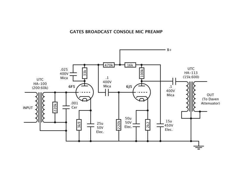
GatesTubeConsoleMicPreamp.jpg


Could I get some info from some of you more knowledgeable tube dudes?  My questions/observations:

1) What is the total gain of this thing?  It seems odd to me that there is no gain control for the mic amp itself, but only attenuation after the fact.  What's to keep it from overloading with loud inputs, or do you suppose it was only intended for low output ribbon mics, etc.?  The mic input (screw terminals) goes directly to the input transformer, so no ability to attenuate beforehand.
2) What is the simplest (best?) way to add continuous gain control to this?  Feedback?  No?  (I'd like some color, but not gnarly).
3) I figure I'd add a pad before the input trafo for loud signals.  Maybe stepped pad.
4) I've seen similar preamp designs but with the B+ coming in through primary winding in output transformer.  I don't believe the HA-113 can handle DC, so this won't work, but for the sake of curiosity, which method is better, and why?
5) What B+ voltage do you recommend, and why?  The psu was apparently outboard as there is certainly nothing inside the console, and there are screw terminals for "6.3" and "B+" on the bottom of the thing that feed the circuit. 
6) Can anyone recommend a good psu design to power 2 to 3 channels of this?
7) Both tubes are the metal / octal socket versions, and the shell (pin 1) is grounded on both.

Pretty much anything you guys can throw at me will be great -- comments, corrections, suggestions, whatever.  I'm definitely on a learning curve with tube stuff, so it's all welcome.  I really just want to make him (and myself) some nice, usable tube preamps, preferably with a little gorgeous tube/transformer color.

Thanks!

JC
 
Hey Joel,

Like you I know very little about tube/valve design but RE not having selectable gain, it was fairly common with not only valve, but solidstate electronics to have a 'fixed gain', which was usefully set by a feedback resistor.

Some had a pad in front of the design of output attenuator, but most had neither.

In the old days if you wanted to make something louder, you moved the mic closer to the source, softer, further away... in some ways I think that this was of benefit as you REALLY needed to use your ears and make committal judgments about placement.

Today we have precision gain structures and deliberate over .5 of a dB differences and rely on the pre to do the work, not the placement... it is an interesting phenomenon I've been thinking about lately.

Engineers of the by gone days had VERY little to work with, yet so many of those records sound so good, look alot has to do with the talent pool, but it still amazes me.

I'm not one of those guys who harps back on 'the good old days and enjoy the advances in technology, but I still feel those limitations bred some fine artist/technical ingenuity.

Best of luck with restoring those pres, let us know what you think of them.

Cheers

Matt
 
Hey, you still got to get me some pics of this thing!  Is there a model # on it? 

These sort of preamps are usually about 40 dB fixed gain with no attenuation, designed for people talking at reasonable levels.  More gain than this was required for most things, which came from the console program amp.    Gain control built in?  Change that 2nd stage 220K grid resistor to a 250K audio pot; might not be a reasonable change to make physically.  Add a standard 20 dB input pad too.  Removing (make switchable) either cathode bypass cap will reduce gain 6 dB.  The first seems the far better choice. 

B+ was probably 250ish.  The next generation of Gates states 180-280 VDC.  Buy a linear regulated adjustable 250 VDC supply from Mouser for $40ish.  Use DC supply or AC filament transformer. 

That output cap is certainly a 1 mfd rather than a 0.1, at least originally. 

The 0.025/33K combo is a high frequency boost that you'll have to measure and see if you like it's effects.  Bypass it for inaudibly higher gain and flat top response, at least not counting the transformer effects. 


Thanks for the input so far.  I'll take some pics tonight for you.  

It doesn't have a model number on it.  If I remember correctly (not at home at the moment) all it says by way of a model is "Speech Input Console".  It has 5 mic inputs, a couple of turntable inputs (mono) and a couple of telephone connections.  It's pretty cool looking (much like the old RCA consolettes with rotary faders), but the wiring is a total mess, meter and other bits are missing.  A previous owner at some point drilled holes in it for colored lights that flashed, and someone replaced the missing VU meter with an unrelated DC meter just to keep it looking complete-ish.

Anyway, the iron is good stuff (UTC HA-series), and I'd like to use those to make some stellar tube pre's.

FWIW, although I'm very curious about the performance of the original design, I'm also considering building something completely unrelated.  Assuming I don't use a variation of the original design, what kind tube preamp would you guys recommend I build with this iron?  Input is UTC HA-100 (non X-version) which I'm thinking using 200:60k, and HA-113 output, wired 15k:600.

Ideas?
 
I have a bunch of the very next generation of Gates preamps, and they are among the best I own, out of some 40+ vintage American tube types.    I'd certainly play with it as is for awhile before going hack crazy.  It's also not terribly far from the design of some of the RCA stuff that people worship. 
 
emrr said:
I have a bunch of the very next generation of Gates preamps, and they are among the best I own, out of some 40+ vintage American tube types.    I'd certainly play with it as is for awhile before going hack crazy.  It's also not terribly far from the design of some of the RCA stuff that people worship.   

Wow... this is intriguing!  What is different about the 'very next generation' compared with these?  Your "among the best" comment compared to 40+ other types is encouraging.

I very much like the idea of using the original design, and I will definitely try it out, but I fear that 40-ish dB just isn't enough for many of the things I do.  I could add another tube for the additional gain, but then I'm wiring up 3 bottles, and at that point I might just use a pair of twin triodes instead of two single triodes and a twin.  

JC
 
Is a 12 or 6SN7 two 6J5s in one bottle did I read  ? if so could you you have 6J5 into 6SN7 or 6SN7s Im sure doug will give us an answer....
After seeing this little circuit and have all the bits in my junk box id like to breadboad this to have a listen dont think I need hi levels myself but if I built more than 2 triode stage id have switches to bypass stages and so on.
Another question for you clever chaps would this design....Is it single ended ? have a more coloured sound than some other designs say like push pull ?
And the DC blocking cap would effect the sound
Theres no HT thru the OP tran in this one is there due to the cap ...I think Rascal seven asked about the differences or advantages or not of the type of design where ht comes thru the OP tran ?....I  cant answer this but would also like to learn

cheers
 
I'm almost always using a pad with these type of preamps; drums, guitar amps, bass amps, loud singers.  Even with ribbon mics.  So they are enough or most things.  Run them into something else with more gain if you need more.  I feed comps usually, and they almost always have gain too.  Those things are going to appreciate in value if you leave'em alone and restore, not a bit if you hack them up.  The 1947 generation went to slightly more porno iron, added a bit of feedback, and put interstage volume control in as I mentioned.  Tubes on those are 6J7 (triode) and 6C5.  There was an alternate version of mine using a 6SN7 rather than 6C5, and coupled as a 3 stage amp.  Note that means the output is the same, the gain is higher, and the input headroom is now obviously lower.  It extends the reach towards lower output mics only, but overloads more easily with higher output stuff. 
 
Its seem a 6SN7 is 2 6J5s in one bottle ...just found one in my junk Im just about to point to point solder this circuit together from junk parts not got original iron but will borrow some Sowters for now.
 
50 minutes 3 cups of coffee and some really shoddy sodering & some crock clips later & its working...have no OP tran at mo Input tran is sowter 9045....I have lots of level softish tone I need to find OP tran to get level down for a better listen
 
Sounds nice with Sowter OP tran 8540 same as for la2a 4:1 i think levels work good for me dont no if will add level pot il find metal box to bolt in in after resoldering nicely.
 
Okay, Gary, you have put me to shame.  I keep looking this thing over and comparing it to other schematics and thinking about what to build, and you've already run with it!  Wow, what a thought... Just build it!

So you're using what is essentially two 6J5's on yours, correct?  The first tube in the console is a 6F5, which has higher gain than the 6J5, IIRC.  And you're happy with the gain you're getting?

BTW, what B+ voltage are you using on it?

Okay, I'm gonna have to rig up a power supply and get cracking...

Crap!  I've got sessions for the next couple of days...  :mad:  Won't be able to jump on it till Thursday.


JC
 
> Is a 12 or 6SN7 two 6J5s in one bottle did I read

You may have read it. It may be true-enough to work. But the 6J5 was a better audio tube. Like the difference between 4x5 Tri-X and 35mm Tri-X film.

You may as well say that 6SN7 is 12AU7. They "are", and they aren't. The 6J6, 6SN7, and 12AU7 are all Modern General Purpose Triodes, with plate resistance limited to suit transformer-coupling, and considerable more Mu than older GP triodes.

6F5 "is" half a 12AX7, with slightly "poorer" specs. These are Resistance-Coupled Voltage Amplifier triodes. The Gm is the same as GB triodes (looks lower because VA triodes aim at lower current than GP triodes), the Mu is raised until typical stray capacitance nips the top of the audio band.

Are you sure about 470K plate resistor? For several reasons, 47K seems much more likely.

Are you sure about the 0.001u at the input? That's absurdly high.

Likewise the shunt on the 33K is more likely a thousand or so pFd than 0.025uFd.

I've never met 0.1u mica in audio; gotta be paper or plastic.

0.1u at output seems skimpy; but I'd have to know T2 inductance and also what bandwidth was claimed.

I really think 6F5 and 470K is wrong; 6J5 and 47K feels right.

Gain:

T1 voltage gain is apparently 17. (It probably should be run as 800:60K.)

V1 gain is likely 35.

V2 gain is probably 8.

T2 gain is 5:1.

It's got such a hellofalot of gain, that either 6F5 is wrong, or it could ONLY be "Speech Console" as it claims to be. It is not true that all old stuff is perfect for modern studio loudness. We were very often working within 50dB of room noise, peaks not a lot over 70dB SPL, with weak-magnet dynamics or even ribbons. Your Fender and AKG will induce sparks at V1 grid.

It's a heresy, but I think your best gain control is to replace the 220K at T1 secondary with a 100K Audio pot. Keep leads short.

Maximum output is not very high either. Maybe +8dBm.

> The mic input (screw terminals) goes directly to the input transformer, so no ability to attenuate beforehand.

You point out yourself: you can put a pad there. That's why it is screw terminals. Real sound techs carry screwdrivers. If all talkers are routinely clipping, insert a pad. A larger console might have dozens of standard-part pads inline and spare here and there, often pre-wired to screws.

> B+ ...through primary winding
> which method is better


Yes.

> and why?

Because.

Because of ALL the USUAL reasons why we have choices. Cost, performance, power, heat, style, parts on hand.

This is, despite T2, a Resistance-loaded stage. Maximum efficiency is 6%.

A Transformer Loaded stage can do 40% efficiency. But the heavy DC in the winding requires a bigger semi-custom transformer and response compromises.

If output had to approach 1 Watt, you'd favor transformer coupling. If output could be 1/100 Watt, then given 1-Watt tubes and resistors, the inefficiency may not matter and resistor coupled is cheaper.

On the third hand, battery-powered field remote boxes favor transformer coupled even if they barely beat +8dBm. Unless the maker just wants to re-box his studio modules and damm the battery cost.
 
JC not trying to shame you I wanna thankyou for put the schematic here you added to my sonic arsnal ha....I just had the parts laying around on my bench soldering iron was on so I soldered away its a bloody mess but works... B+ is about 250.....level was good for me tho I only have a simple set up I just record vocals home made tube mic I have various DIY tube pres using Sowter & scrounged transformers I have DIY limiters again sowter into M Audio box into PC....I dont really no how to measure the level but DIY Ela M251 mic into the gates circuit into DIY ba6a worked well the gates had a little less level the my fav DIy V72 so I just turned up the inut attenuattor of the limiter.. hope that helps....was thinking about your plans for the gates maybe you could strike a deal with yr  friend  & make him from scratch a pair of pres based on the gates using new transformers then keep the gates whole & original as doug says they go up in value & be a shame to disasemble the gates.....anyway just a thought.

PRR hi yeah I read that about the 6SN7 had one to hand and went ahead and soldered ....so would be worth a listen to 6J5s then......

I forgot to post earlyer that the 220K & .001 across the input took away too much hi for me so i took them off.

Il take .025 bypass off and try something else

& il swap the 470K i had about 400K there il try 47K then

I used 1 u for DC blocking cap as doug suggested.

Cheers.
 
PRR, the 470K indeed looks high, but may be correct.  I've seen other stupidly high plate resistors in Gates gear of this era, and usually end up strapping something else in parallel to cut the value down.  If I didn't say it earlier, this thing would be 1947 or earlier; pre-SA series.  Gates did use 6F5 and 6SF5 before then. 
 
Swapping to 47K and taking out the 0.025 bybass cap didnt seem to make any audio difference to my breadboad version....only a quick test I recorded verse of song & swapped each component.
 
PRR said:
Are you sure about 470K plate resistor? For several reasons, 47K seems much more likely.

Yes, I double checked it.  I cut one end and measured it, and also the color code is yel/purp/yel/silv = 470k.  Same on every channel, and the resistors appear stock.

PRR said:
Are you sure about the 0.001u at the input? That's absurdly high.

I believe that's correct.  A large-ish ceramic disk with ".001 10%" marked on it.  Didn't cut it loose and measure it since the markings are so clear.  Same on every channel.

PRR said:
Likewise the shunt on the 33K is more likely a thousand or so pFd than 0.025uFd.

Actually, I got that value froma new mica that was stuck there on one channel as replacement for the original.  The other channels have "Micamold" caps with the three dot color code.  Color (left to right along the arrow) are red/black/orange = .02 not .025.  One every channel except the one that had the replacement. 

PRR said:
I've never met 0.1u mica in audio; gotta be paper or plastic.

Actually these are new caps on all but two channels... look exactly like big micas to me, but I suppose could be some brand of film.  The two oddball channels appear to have original Sprague caps that are plasic shells (black plastic with yellow printing) that still .1uF 400v caps.  The Micas were clearly added later (they're still shiny, actually... not dirty like the rest of the bits down there), but they are also .1uF.

PRR said:
0.1u at output seems skimpy; but I'd have to know T2 inductance and also what bandwidth was claimed.

The original Sprague is, indeed, a .1uF on the output.  I tried to measure the inductance of T2's primary windings, but it is too high for my meter (a Meterman 37XR).  FWIW the secondary inductance measured 5.5H, if that's helpful at all.  It is a UTC HA-113 wired 15k:600.  Not a fat clue about bandwidth claimed by Gates for this thing.

PRR said:
T1 voltage gain is apparently 17. (It probably should be run as 800:60K.)

T1 is a UTC HA-100 wired for 200 (250):60k according to UTC data sheets I got from CJ a couple years back.  I can connect the primary for 500 (600), but not 800.  Can you explain your reasoning behind your suggesting for connecting it 800:60k?  I always love your posts, because you not only give suggestions, but give reasoning and theory behind the suggestions.  It's always an education, and that's what I'm hoping for.

So based on all of this, what changes would you recommend to optimize this circuit for general, HQ studio recording use?  I'd prefer as much gain as is practically possible (a solid 50dB would be nice if possible), but don't want to compromise audio quality.

And, FWIW, my desire for these are to have a 'tubey' quality (that is, some second harmonics -- that kind of thing people tend to want from old tube circuits, even though many tube circuits are quite linear).  I have already built Jakob's G9, and love it, but it is a clean preamp (the cleanest I have in my otherwise Neve and API-equipped facility).  I'd like something tube with a more vintage coloration that is flattering on stuff.

To this end I'm considering using a psu with a tube rectifier to get a little 'sag' (guitar amp terminology, I know) in the thing.  I know a guy with a rack of RCA BC2B preamps that he powers with the psu from an old Fender Bassman head (tube rectifier -- don't know which, though.  Fender used various ones through the years).  Those pre's sound gorgeous!

I know Steve Firlotte of VAC RAC and Inward Connections fame is zealous about the use of tube rectifiers in all of his tube power supplies. 

And regarding a tube rectifier, the 5Y3 is the one lots of folks like because of its relative slowness/sag, but I've read that many people think the GZ34 (I think that's the number) is the 'best' tube rectifier made.  Any comments/observations/suggestions here?

A 20dB pad on the front is a forgone conclusion, as is a pot between stages to modify level.  But what other changes would make this circuit better for general music (full-bandwidth) applications?

Thanks so much for your input and the educational explanations, PRR!  This is no doubt helpful for many folks around here, not just me.

[ put old 'thumbs' emoticon here  ;D ]

JC


> 470K indeed looks high, but may be correct

On its own, it might make sense. I've seen that high in late tube radios.

Although stray C will kill everything above the audio band. That's what you want in an AM radio. It may have been accepted in 1947 broadcast. It may have been the fashion at Gates.

The 220K at the next grid casts doubt. You can down-gear from plate to grid but there's rarely a reason to do so. And 220K gridleak is very conservative. Maybe the 6F5+470K is a one-off high-gain hack on a conservative standard design. Gates was never huge and often willing to do specials.

Looking again, I wonder why the first stage B+ is not decoupled and the second one is. This is so odd that I suspect the R and C topology has not been reverse-engineered correctly. At a minimum, I'd take 1st stage B+ from the 16K(?)+15uFd node. Or you could argue 470K dropper and 0.02u to Ground.... similar hi-Z decouplers were common when electrolytic caps leaked bad, and 470K+0.2u would at least knock the buzz down some.

Assuming the 33K and 0.025u are as shown, why? With 470K||220K, it does nothing. With a 47K load, it is a several-dB top-boost. And it "could" be that the 0.001u at input IS correct, an extreme-RFI measure, and the plate-load top-boost bumps 2KC-5KC to get back to nominally flat.

Great transformers. Probably great metalwork. Genuine dust of ages. But I'm not sure where they fit in the modern studio. I hate to see them cut-up, and am not inclined to re-design for free.

> worth a listen to 6J5s

It's cork-sniffing. I do believe that 6J5 and 6J7 are benchmark audio tubes, and that 6SN7/12AU7 is bent differently. But in this preamp input, no difference.
 
> not 800

Whatever is higher than 200.

1:17 input ratio is higher than you need in modern studio. Steps usually go 2:1 voltage 4:1 impedance (dual winding series:parallel) so I'd guessed 800. But it's all nominal.

> get a little 'sag'

Class A amplifiers won't sag. Opinions on hollow rectifiers vary; please yourself.

If you want a "color" preamp, start with +300V and find a way to adjust it down to 200V, 100V, 50V... until you get your desired color. Since the total demand is just a few mA, a MIL-spec 100K 2-Watt pot can do it.

> optimize this circuit for general, HQ studio recording use?

That's a bottomless can of worms I won't go into. Except: if I was going there, I would not start here. Stick plenty of padding front and back, hammer it, enjoy it for what it is.
 
Great stuff.  Thanks.

I just went back out into the garage, redrew the circuit on a new sheet of paper and then compared it to my previous drawing, and it appears identical.  I compared channels too, just to ensure that something isn't screwy between channels.  It all looks good.

Is there any reason you can think of that they would leave off the decoupling on the 6F5 stage?  I'm totally new to this, so it's totally understandable to question my reverse-engineering, but a second drawing shows the same thing (and then I triple checked it just to make sure).

Could this just have been an oversight at the shop when they built this thing, and no one has ever caught on?  Or perhaps the factory decoupling was removed by an uninformed service tech a long time back?  What is the advantage of the decoupling at this stage?

Also (or?) do you suppose it could have been a mistake that they grabbed 470k instead of the 47k you expected?  It's just one color band different.

I know I sound like an idiot, and with tube stuff I am.  I'm not really wanting anyone to design or modify this for me... I'm cool with tinkering, but a little more understanding of why stuff is probably wrong (or certainly unusual with the current circuit) would assist me in my pursuit.  I have considered just building an Altec 1566A circuit with the UTC iron, but I'm interested in exploring this circuit in an attempt to learn about the hollow state world.  This has been a helpful thread so far.  I will continue to chew on what has been shared here and digest as much as possible.

Thanks so much,

JC.

 
Back
Top