Hotrod Build Thread

GroupDIY Audio Forum

Help Support GroupDIY Audio Forum:

This site may earn a commission from merchant affiliate links, including eBay, Amazon, and others.
I just realized that the two transformers that I have are actually Marinair 31267/s or T1442. It has a different pinout than a 1452. 5 on one side (pins 2-6) and 4 on the other (pins 7-10). Does this pose a problem for wiring as a 10468?

HEEEEEELLLPPPP :shock: :shock: :shock:

I'm itching to fire this thing up :twisted:
 
I can only seem to get signal on the -30 and -35 dB settings and it has plent of hum. Can somone point me in a direction to find the problem. I thought someone had this problem but I can't seem to find the thread.
 
bluezplaya: Please provide me two links. One to the JLM site that talks about the wiring and one to the Maranair 31267 spec sheet. I'm sure we can figure this out.

quavatone: Did you jump positions 7 to 12 on the first deck?
 
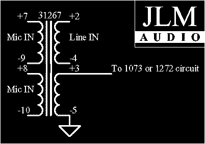
From what I can tell, just go by the pin numbers shown on the JLM site. It looks like JLM used the 31267/s in their tests. I don't think it matters that the pin arrangement is physically different than the 10468.
 
31267%20as%2010468.gif


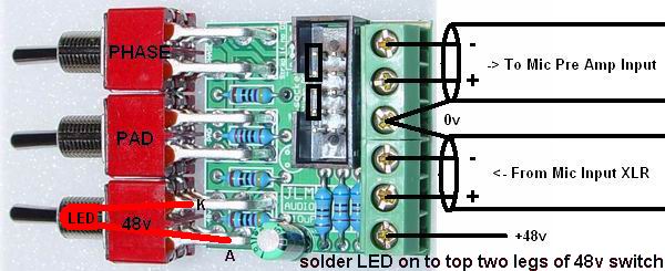
Alright Greg, as I've studied this picture on the JLM site even more, I come to see things a little clearer on the transformer wirings (can't you tell I'm not an expert on transformers :oops: ) I have one more question before I fire this thing up for the first time. Going from XLR input to the JLM Go Between, I need to come out of the GB to the input transformers (pin 7+ and pin 9-) but where does 0v go to on the transformer? Pin 6 or to a chassis ground?

48vPadPhaseDIwiring.jpg
 
Grounding for this project needs to be thought out a little. Just make sure everything only has one path to ground.

One option is take the 0V to pin 5, then take pin 5 to the input of the Hotrod board.

I will look inside my Hotrod tonight to double check my grounding to tell you exactly how I did it.
 
Duh, OK I now see the solid lines on the posititions that SWB has resistors attached. Thanks, I'm so glad it's something simple like that :grin:

BTW in the above post re the Pin 5 grounding method. You are talking about pin 10 on the 10468, right?
 
Alright, we have liftoff!! :grin: Everything seems to be working so far so good for channel 1. Phase, pad, 48v rockin' and rollin'. Input sensitivity switch, output volume working fine. I do have that nasty ole' HF that folks have been talking about with the 31267's :roll: . I am listening on my cheap-o computer speakers using 1/4" TRS out. I haven't done a thorough star ground setup yet though. That'll be next, just making sure the channels were working. On to channel 2!!!

Adam
:sam: :sam: :sam:
 
[quote author="guavatone"]BTW in the above post re the Pin 5 grounding method. You are talking about pin 10 on the 10468, right?[/quote]From looking at the diagram, yes, that'd be pin 10 of the 10468. Keep in mind I've never wired one of these, but I think I'm correct.

Very nice, Adam. You might need to load the 31267 differently if it is ringing. Perhaps a zobel is needed. What did Kevin do?
 
I don't know what Kevin did for his. I do know that I've seen plenty of talk on the forum about wiring to eliminate the hum. I'll just have to snoop around and see what I can find. I'll be posting some pictures of this thing before long. This was actually a fairly easy build. The hardest part was reading up, which wasn't too hard either. I think this was the first build of mine with no hangups from the start, other than the JLM Baby Animals I've got. Those are super easy :green: .

Adam
 
Quite a bit HF garbage but the hum is gone. I'll keep it a secret what I did wrong on this one. :cool:


Do we need to jumper 12B to 8B on the switch or is this on the PCB?
 
OK 12A through 7A are jumpered

I have no signal from 1-4 and 9
pos 8 is intermittent.


The HF stuff is a little better with a brand newly stuffed 283 card. The old/noisy one is an original with new el-caps but fixing that deserved it's own thread......


Any help appreciated.
 
Okay, I am tired of f@#king with this grounding issue on the Neve. This shit is just way too complicated at 1am. I need someone to help pull me out of this hole I'm digging myself in :sad:

1. I'm using JLM AC/DC 3 Rail PSU, Output Transformers, and Go Between
2. Both XLR in and TRS out PIN 1's (audio ground) are all connected to PSU 0v
3. Pin 6 of 31267 and Earth from Hot Rod boards both connected to chassis, which is connected to earth pin of AC inlet.
4. 0v from PSU is connected to earth ground from AC inlet
5. The way it is hooked up now, my 1 watt 12ohm resistors on the Hot Rod boards are smoking :shock:

Questions:
Do the output transformers need to be earth grounded? If so, how?
 
[quote author="bluezplaya"]Okay, I am tired of f@#king with this grounding issue on the Neve. This shit is just way too complicated at 1am. I need someone to help pull me out of this hole I'm digging myself in :sad:

1. I'm using JLM AC/DC 3 Rail PSU, Output Transformers, and Go Between
2. Both XLR in and TRS out PIN 1's (audio ground) are all connected to PSU 0v
3. Pin 6 of 31267 and Earth from Hot Rod boards both connected to chassis, which is connected to earth pin of AC inlet.
4. 0v from PSU is connected to earth ground from AC inlet
5. The way it is hooked up now, my 1 watt 12ohm resistors on the Hot Rod boards are smoking :shock:

Questions:
Do the output transformers need to be earth grounded? If so, how?[/quote]


re # 3: Hot rod Audio ground next to +24V should go to JLM 0V. Assuming you are using a 10R and .1uF cap on the JLM, and taking the ring connector to chassis on the JLM. Your 283's have a potential ground loop the way you have it wired.

Ain't it a bitch. I am having a hell of a time with mine. many details on these.
 
I'm using this JLM wiring diagram along with Joel's Neeb wiring notes (not sure where they are). Hope this helps.
http://www.jlmaudio.com/JLM%201290%20wiring%20overlay.pdf
 
Adam:

I'd recommend drawing a wiring diagram of the whole layout. It really helps visualize things. Then post it here so we can comment on it.
 
Back
Top