JLM Baby Animal

GroupDIY Audio Forum

Help Support GroupDIY Audio Forum:

This site may earn a commission from merchant affiliate links, including eBay, Amazon, and others.
i plan two build two (high gain) units to start with, one of each type of opamp.
what is your opinion of OEP/OPA2604 versus the OEP/99v? (where was that review someone did?)
Will be back further in this thread. Make sure you have OEP262A3E with Mu can or OEP262A3C.

is the Hybrid opamp the OPA2604, or is it a different opamp altogether?
There is a circuit on the hybrid web page http://www.jlmaudio.com/JLM Hybrid opamp.htm

(i have six of fabios 2520 descrete opamps - i'll have to try them, when i do the build - i presume they share pinouts)
Yes 990 and 2520 and 99v have the same pinout.

another question - will i be able to achieve variable impedence with the OEP trannie?
Yes it is in the tables on the BA page. http://www.jlmaudio.com/Baby_Animal_Mic_Pre.htm

Really? I totally missed out on that and wired it to + and -
Ok I should clarify this. When using a output transformer connected to +out and -out with 99v it has 2 x 470uF caps and 2 x 51R in series with the primary and will still work fine as long as the strap between pin 4 and 7 on the dip8 IC socket is in. But wiring the transformer to +out and 0v cuts this back to 1 cap and 1 x 51R resistor in series which just means less parts and losses in the output path.

But when using a dual dip opamp like opa2604 with a output transformer still use +out and -out or you will lose 6dB of gain. But with 99v use +out and 0v
 
Thanks! Will do, I need to redo some of the wiring anyway.
So basically I could've left out the cap, the resistor and the 4-7 pin strap from the pcb?
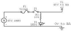
Oh, and the fuse in the pic, I haven't seen anyone use one in their builds.

PowerLED.gif
 
Okay,

I just got done making another Animal Pre Rack, this time with 1 channel of JLM1:4 Trafo and JLM99V DOA, the other is an OEP A262A3E with Can, set to LOW Gain and has an OPA2604 IC in it, neither are transformer balanced out.

I made a quick clip of each channel for you, it is in no way definitive, but paints a basic picture. So far we have heard about the way they sound in words, now hear it.

Both takes were done with a Violet Design Black Knight mic about 5 inches away from the 12th Fret of my Custom Built Acoustic, no EQ's, compression or any processing, as is sound.

JLM1:4 + JLM 99V DOA (1.8mb)
OEP A262A3E + OPA2604 IC (1.8mb)

First impressions is that the JLM1:4 and 99V is a quite a bit darker with a rich low end and smooth highs while the OEP seems to less low end, but tight nonetheless with a bit more mid range and shimmering highs, both sound great and will have their uses.

Cheers

Matt
 
Anyone from the states order from JLM? Joe sent mine out on August 8th, and I still haven't received them. Should I be worried or is the US customs office slower than dirt?
 
matta: Nice tests. Yeah there is a significant bassboost with the JLM compared to the OEP. This would kick butt on thin bright voices I think.
 
Anyone from the states order from JLM? Joe sent mine out on August 8th, and I still haven't received them. Should I be worried or is the US customs office slower than dirt?
Well we haven't lost a parcel in 22years and we send about 30 parcels a week to the USA but we have had several turn up late either due to customs hold up or Aust post missing the Air Mail sticker and sending it Sea Mail. But most delays are due to no attempt of delivery docket being left and the parcel sitting at a local post office. Same goes for customs waiting to hear from the receiver. So best thing is to see if your local post office and customs office are holding any parcels in your name. But I would wait and see if it shows up by Monday next week as today would have just been the end of the 10 working days it can take for Air Mail but if Customs open it add 1 extra week.

matta: Nice tests. Yeah there is a significant bassboost with the JLM compared to the OEP. This would kick butt on thin bright voices I think
Thanks for putting up the samples Matta :cool:

The JLM14 if flat in its low end response and goes down much lower than the OEP262A3C. The OEP starts rolling off at just above 30Hz. But if you drive the JLM14 with higher level by not using the pad it fattens the low mids in a nice way without getting muddy on bass and drums etc.
 
[quote author="JLM Audio"]
The JLM14 if flat in its low end response and goes down much lower than the OEP262A3C. The OEP starts rolling off at just above 30Hz. But if you drive the JLM14 with higher level by not using the pad it fattens the low mids in a nice way without getting muddy on bass and drums etc.[/quote]

Hmm...I have to rethink my choice of transformers :? Was going for the OEP but now I don't know.
 
[quote author="therecordingart"]Anyone from the states order from JLM? Joe sent mine out on August 8th, and I still haven't received them. Should I be worried or is the US customs office slower than dirt?[/quote]

My power supply showed up very quickly. Your stuff may be stuck in customs.

Cheers,
Zach
 
Not needed with your transformer. It is the RL resistor for the OEP, with the JLM you would have used the 10K in its place, so fear not :green:

Cheers

Matt
 
Awesome....a few more things....

I have 3 diodes (two big ones and one small one), but only two spots for diodes. Which do I use?

There is also a grey diode-ish looking part....what is this and where does it go?

Do I use the regulators or not? I have the smallest of Joe's power supplies. If so, which side is which?

Lastly, do I need to put in any jumpers for the parts that I leave out?
 
If you are using the small +48V supply you don't need any diodes or regs if you are using the OPA2604 opamps.

No jumpers are needed except for the the darlington transistors (regulators), where you will need to put a jumper between the E (Emitter) and C (Collector).

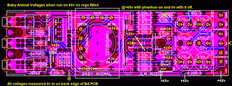
See the yellow lines below:

Baby%20Animal%20PCB%20voltages.gif


May I also suggest to any builders that on first power up you DON'T fit the Opamps. I er on the side of caution and choose to do this to check that the voltages are correct.

The voltages are stated in the above drawing, for obvious reason the output and - rail lytics caps will not measure +24V as indicated until you insert an opamp, but it will at least show you that your input voltage is correct and not say +48V, which is ABOVE the max V input for an OP2604.

Cheers

Matt
 
Last few questions......

Where to I connect the black wire from the JLM14?

Do you wire it from underneath and solder to the top of the board?

Which 10k resistor and I supposed to leave out? (I put them all in)

This is the dumber question....

I have no clue how to wire up the gain knob and XLR connectors!?!

Last....

I ordered the JLM front panel and a par-metal enclosure. On the JLM site there aren't any mounting holes through the front panel to mount it to the enclosure. This sounds dumb, but how was that done?
 
TheRecordingArt,

Where to I connect the black wire from the JLM14?
I snipped mine because it is not used.

On the JLM site there aren't any mounting holes through the front panel to mount it to the enclosure.
I use Par-Metal for all my projects. Use the front panel from the Par-Metal case to use as a template for the 4 screw holes that need to be drilled in the JLM front panel. I just laid the PM panel over the JLM panel and made my marks and drilled away.

I have no clue how to wire up the gain knob and XLR connectors!?!
Take a look at my picture. You'll notice the red wire on the left leg of the pot goes to "gain" on the PCB. The middle and right leg are wired together and the black wire (ground/0v) on the right leg is going to the next pot. You would send that black wire to the "0v" on the corresponding PCB, which is the middle screw terminal. Or if you have more than one mic pre ( I have 4 in a chassis), you can wire one mic pre (0v) to it's pot, and then wire to each other pot in series. (see pic 2)

XLR's wire up like this:

Pin 2 of XLR Input to "in+" of pre
Pin 3 of XLR Input to "in-" of pre
Pin 1 of XLR Input to "0v"
The same applies for Output only wiring to "out+" and "out-" on the board.

ba2.jpg


ba1.jpg


Drink a few Newcastles and take your time :sam: :sam: :sam: :sam: :sam:

Adam
:sam:
 
One extra thing, its usually good practice to tightly twist the gain wire (and its ground wire) and make both as short as possible. This also goes for the other audio wiring. The mic input cable should be shielded and the output wires tightly twisted.

Also its a good idea to cover the end of the snipped black wire (on the JLM 1:4) with heatshrink or tape, otherwise it can short out the input.

Like Matt said, definitely check the voltages at the opamp sockets when you first power it up without the opamp plugged in. I do this every time.

Just take your time and be as neat and methodical as possible, and your reward will be a pre that works first time and goes for decades without a fault.


M@
 
One extra thing, its usually good practice to tightly twist the gain wire (and its ground wire) and make both as short as possible. This also goes for the other audio wiring. The mic input cable should be shielded and the output wires tightly twisted.

Also its a good idea to cover the end of the snipped black wire (on the JLM 1:4) with heatshrink or tape, otherwise it can short out the input.

Like Matt said, definitely check the voltages at the opamp sockets when you first power it up without the opamp plugged in. I do this every time.

Just take your time and be as neat and methodical as possible, and your reward will be a pre that works first time and goes for decades without a fault.

What he said :green: I've heard 2 minds think alike, but 2 Matt's? Hah Hah

Follow Matt's advise it is good info for all the projects you might tackle.

Also I like colour coding my cables, it makes troubleshooting easier. For example I make all my ground and 0V wires green, Audio In and Out + is Red, While Audio In and Out - is Black. The same for + and - voltage rails and I used purple on these pots, but sometime will use blue and Phantom is normally Yellow.


Cheers

The 'other' Matt

(I would day Australian Matt but that would confusing things since by birth/citizenship I'm an Aussie to... how weird)
 
Hey Matt, those samples are great. To my ears they show the differences between those two transformers/opamps perfectly. Anyone wanting to know about sound differences listen to those clips before asking!

For some extra info, if you can imagine the smoothness of the 1:4+99V but with less low end and more upper mid emphasis, thats what the OEP+99V sounds like. The 1:4+OPA2604 sounds like the bottom end of the 1:4+99V sample with the high top end of the OEP+OPA.

Confusing enough?


M@
 

Latest posts

Back
Top