This is the final build post.
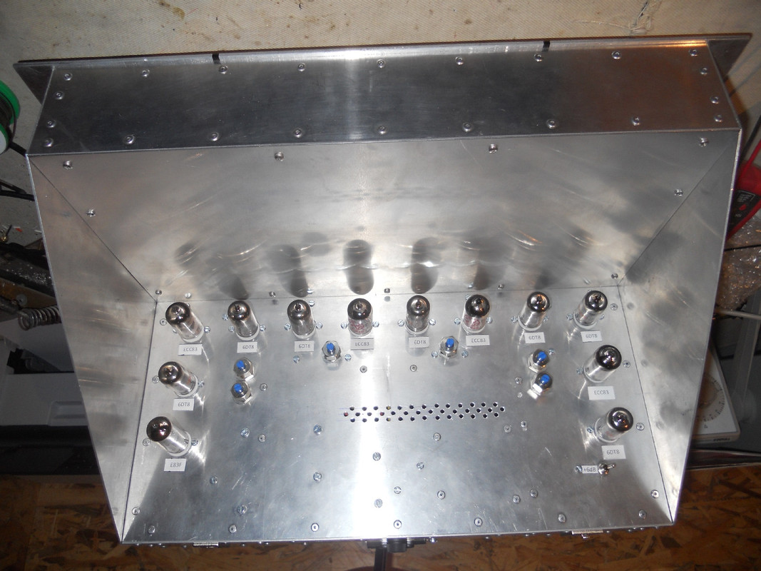
There were so many tubes, I had to label them inside and out to keep track of it all.
It looks overwhelming but it can be done by very carefully marking your progress on a build copy of the schematic.
I had to drill extra ventilation holes for the power supply, there were more on the base cover to get some convection currents going.
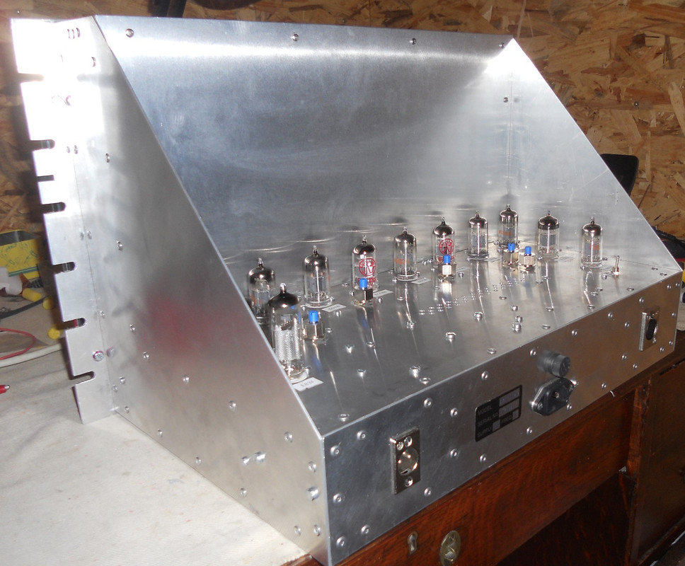
The blue presets are used to set the outputs of the six sections according to the original schematics.
The supply voltages I used were 280V for the ECC83 tubes, 260V for the output E83F and plus and minus 100V for the cathode followers. I prefer to use 6DT8's which are a more robust 6V version of ECC81's. The maximum voltage for a half watt resistor with this current would be 139V, so I preferred to stick to plus and minus 100V. There is no info on voltages in the manual, so I had to work them out for myself.
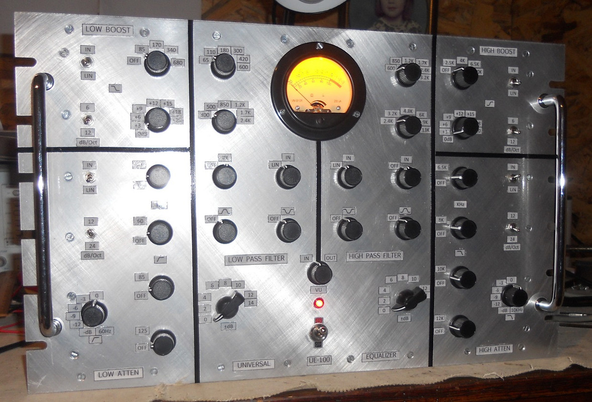
This shows the front panel lit up, I hope Ian manages to make sense of it all!
Thanks to everyone for your support on the project, it has been the most challenging I have ever done, especially with the domestic situation in chaos at the beginning.


