LA-4 Help Thread!

GroupDIY Audio Forum

Help Support GroupDIY Audio Forum:

This site may earn a commission from merchant affiliate links, including eBay, Amazon, and others.
hi, I decided to give it a try and build a dual la4 (with stereo linked switch).

Just wanted to ask if there are any other PCBs (apart from the 2 la4 of course) I should consider buying.
I don't know, maybe a relay bypass or psu board or anything like that? 

thanks
w
 
The PSU is part of the PCB. If you want add a relaybypass, then you'd have to buy a board for that, or perfboard one yourself, yes.
In case you're building a dual LA4, you only need to populate one PSU part of the 2 PCB's.
 
thanks your help helterbelter. What about the 'link' switch? Is there any pcb or schematic available?
 
warpie said:
thanks your help helterbelter. What about the 'link' switch? Is there any pcb or schematic available?

It's just a switch. either both pcb's are connected to eachother or not.
 
And yes, there is a schematic available. Check the very first post in this thread.
I'm probably missing something but there's no 'link stereo' info at the schematics.

I assume is a bit more complicated since with one switch I have to link 4 different controls (ratio, thresh, makeup and meter) but anyway, thanks for the help  :)

 
As Luney said: Read the first post!

There's a link to the manual, at the end of the manual there are the schematics (LA4 and LA4A).
On the left side of the schematic just under the input strip you can see the "stereo connection"
and stereo "on/off" switch.

I dont think you can manage to control four functions with one switch... ;)
Better use a switch for the ratio/meter and pots for tresh/output, as in the schematic.  ;D
Good luck,

Anders
 
warpie said:
thanks your help helterbelter. What about the 'link' switch? Is there any pcb or schematic available?

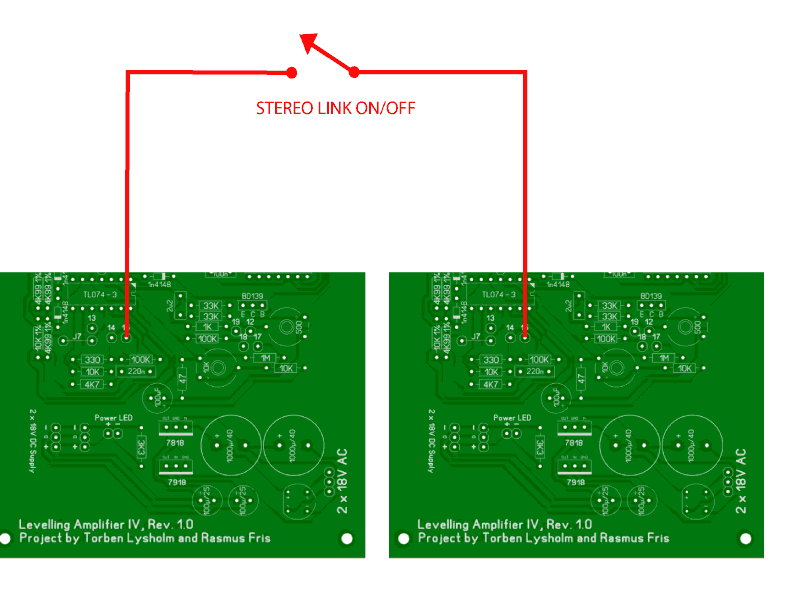
All you do is connect the Control Voltage side chain from each board together by joining pin 15 from each PCB.

You can do this with a switch on the front panel if both your units are in the same enclosure. If they are in 2 separate boxes you will need a switch on each unit and a jack or phono plug at the back to link the two units.

Makes sense?

I hope this illustration helps.

J
LA4-Stereo-Link.gif
 
Just a quick question. One of many I'm sure. I was reading over the G9 project (which is next on the docket), and I read that when using 110V mains, you have to wire the transformers primary in parallel to achieve 110V, and then wire the secondary in series to bring it back up to 220V. Is this the same sort of situation? Probably a stupid question, but I thought I'd check.

 
Hi... I am soon to be drilling my case out for this project and I haven't got my PCB yet. Does anyone have the physical dimensions for the PCB so I can put my mounts in?

Thanks

Nick
 
Hi guys !

Stereo-unit done, wiring completed... now CALIBRATION.... :)

I could use some help in doing this...

I have a software tone generator, my DAW, a multimeter and a VU-meter.

I'm reading chapter (or whatever it's called) 11. Meter calibration in the manual and trying to get my head around how to do this.

First question: dBu ? how do i measure 0 dBu and also 10 dBu on the output ? 0dBVU = +4dBu ?
can i strap 2 600 ohm resistors across the output and a VU-meter to get the level right ?

Any practical tips are most welcome.
 
Ok.

Is it important to have a 600 ohm load on the output ?
I guess I can just plug it into the G9 ...

Sorry bout all these questions, but I'm tryin' to learn something here...  ::)
 
Luny Tune said:
Use the VU meter on the output and the multimeter on the input.

If you're using a multimater be aware of the fact that many digital multimeters have a very limited frequency response when measuring ac volts.  It maybe worth checking the specs of your meter so that you can inject a signal within the frequencies that is it acurate.
 
Rob Flinn said:
Luny Tune said:
Use the VU meter on the output and the multimeter on the input.

If you're using a multimater be aware of the fact that many digital multimeters have a very limited frequency response when measuring ac volts.  It maybe worth checking the specs of your meter so that you can inject a signal within the frequencies that is it acurate.

Yup. I'll measure the voltage at 50 Hz, then switch to 2K.
 
Hey Guys,

First of all, thanks to Luny Tune for the project... excellent work, well documented.

So this is one of my first projects and it's I'm just getting my head around schematics. I've just been working out the wiring to the different numbered pads on the board and wanted to double check with you guys if that's ok?

2+3: to a simple toggle switch for input range?

6+7: Input overload LED

8, 13, 14: to the threshold pot? 8 to the clockwise (or maximum) spot, 13 in the centre and 14 counter-clockwise?

10, 26, 27: to output pot? 10 clockwise or maximum, 26 in the middle and 27 in the maximum or counterclockwise position?

28, 29, 30, 31: meter switch. I'm still struggling with which pad goes to which pin on the switch but this is my best guess:
Meter negative: C on switch
Meter Positive: A on switch
30: 7 on switch
29: 2 on switch
31: 8 on switch
That might be completely wrong, as I said I'm not understanding it 100%

12, 17, 18, 19: Ratio Switch. Same deal... not exactly understanding this.
12: A on switch
17: C on switch
18: 11 on switch
19: 1 on switch


If anyone could steer me in the right direction on these ones that would be amazing. Thanks so much in advance,

Nick.
 
Hello guys,
do you think it is do-able  to replace the meter with leds?
would it be ok to drive leds with a tl074 through a resistor network, then?
I will loose the original esthetics, but at 40mm panels width, it's going to be difficult to fit a small meter..
another possibility is to implement the same kind of meter as in the GSSL..
thanks
best
Maxime
 
Led meters ? Use an LM3915 as driver. In case you need a pair of small VU meters, I have a few spares from Teac machines. The GSSL meter is a PPM, not VU. I'm not sure if that will function adequately.....

Nick Franklin said:
2+3: to a simple toggle switch for input range?

6+7: Input overload LED

8, 13, 14: to the threshold pot? 8 to the clockwise (or maximum) spot, 13 in the centre and 14 counter-clockwise?

10, 26, 27: to output pot? 10 clockwise or maximum, 26 in the middle and 27 in the maximum or counterclockwise position?

This is correct, yes.

Nick Franklin said:
28, 29, 30, 31: meter switch. I'm still struggling with which pad goes to which pin on the switch but this is my best guess:
Meter negative: C on switch
Meter Positive: A on switch
30: 7 on switch
29: 2 on switch
31: 8 on switch
That might be completely wrong, as I said I'm not understanding it 100%
Allmost correct.
-meter goes to A,
+meter goes to C.
28 goes to 1
29 goes to 2, and via a resistor of 4k7 to pin 3.
30 goes to 7
31 goes to 8 AND 9.

Nick Franklin said:
12, 17, 18, 19: Ratio Switch. Same deal... not exactly understanding this.
12: A on switch
17: C on switch
18: 11 on switch
19: 1 on switch
Correct, but not complete yet :
12: A on switch
17: C on switch
18: 7,8,9,10, and 11 on switch
19: 1 and 2 on switch.
Between 2 and 3 a 3k6 resistor and  between 3 and 4 a resistor of 5k6.
 
Back
Top