You are using an out of date browser. It may not display this or other websites correctly.
You should upgrade or use an alternative browser.
You should upgrade or use an alternative browser.
LA-4 Help Thread!
- Thread starter Luny Tune
- Start date


Help Support GroupDIY Audio Forum:
This site may earn a commission from merchant affiliate
links, including eBay, Amazon, and others.
Nick Franklin
Well-known member
- Joined
- Feb 16, 2009
- Messages
- 118
Helterbelter, thankyou so much
Piotr
Well-known member
Hi to all of you,
I'm getting to the end of the project and a couple of questions remain. Just to be sure I'll ask anyway...
R11 - 2.2K should be wired between the Output Level pot and the Threshold pot along with an screened double link to pads 8 and 9 on the board. Please correct me if I misred or misinterpret the schematic...
There are two 47 ohm resistors on the BOM but I do only find R35 on the schematic and on the board so I have a 47 ohm resistor left ??? What am I missing here ????
Appart from this, this is a wonderful project, thanks Luny Tune. As soon as I'm finished I'll post an updated BOM with Farnell order codes and all the info I've gathered on the way. Just want to be sure I'm not spreading unverified infos here...
Thanks for your help, cheers, Piotr.
Rybow
Well-known member
My PCB from Gustav arrived today! I am so stoked to get started on this puppy. The PCB is really nice! Alrighty, time to finish buying parts, and get to work. I was even able to get my hands on a drill press attachment for my drill. I know, not as good as a real drill press, but it was free!
Luny Tune
Well-known member
Sorry, Plotr. I'm not understanding "screened double link". What is that?
Let me try to explain and then you may not have to explain after all! ;D
What you need first and foremost is a lead from Pad 8 to the Threshold pot's Clockwise pin + a lead from Pad 10 to the Output pot's Clockwise pin.
You can then choose to either...
...use screened cable for the above and solder the screen around the lead from Pad 8 to Pad 9 and the screen around the lead from Pad 10 to Pad 11
...or do as I've done just twist the leads from 8 with the leads from 13 and 14 (14 is ground) and the lead from 10 with the leads from 26 and 27 (27 is ground). That works too.
Then you just solder the 2K2 resistor between the two Clockwise pins on those two pots.
AND REMEMBER to solder a piece of wire between the two Counter Clockwise pins on those pots too! that is to compensate for an error in my design where I somehow missed the little detail of connecting ground to the sidechain circuit... :")
Let me try to explain and then you may not have to explain after all! ;D
What you need first and foremost is a lead from Pad 8 to the Threshold pot's Clockwise pin + a lead from Pad 10 to the Output pot's Clockwise pin.
You can then choose to either...
...use screened cable for the above and solder the screen around the lead from Pad 8 to Pad 9 and the screen around the lead from Pad 10 to Pad 11
...or do as I've done just twist the leads from 8 with the leads from 13 and 14 (14 is ground) and the lead from 10 with the leads from 26 and 27 (27 is ground). That works too.
Then you just solder the 2K2 resistor between the two Clockwise pins on those two pots.
AND REMEMBER to solder a piece of wire between the two Counter Clockwise pins on those pots too! that is to compensate for an error in my design where I somehow missed the little detail of connecting ground to the sidechain circuit... :
Here's an ugly sketch of the off-board wiring that i drew for myself. Maybe someone can make a better one....
NO guarantee that it's correct, but I´ve wired and tested my comp and it seems to work.
I haven't calibrated it though.
So CHECK with the SCHEMATIC. If someone finds an error, please let me know.

Link to the pdf: http://www.bitterend.se/LA4-Offboard-Wiring.pdf
NO guarantee that it's correct, but I´ve wired and tested my comp and it seems to work.
I haven't calibrated it though.
So CHECK with the SCHEMATIC. If someone finds an error, please let me know.
Link to the pdf: http://www.bitterend.se/LA4-Offboard-Wiring.pdf


Piotr
Well-known member
Hi guys !
Sorry Luny Tune for my "screened double link" trouble !
I was refering to the schematic and to the two connections to the Output and Threshold pots (#4 and #5 on the schemo). These two being screened I refered to them as a "screened double link"... I agree that it sound a lot more complicated then it is, I must have been tired !!!! My kids have a lot of energy these days, they kill me !!!
Anyway, thanks for clarifying this, I had understood the schemo right, but my english made it sound complicated...
I have noted that we have to correct the missing ground in the sidechain.
Finally I'm still stuck with the remaining 47 ohm resistor (there are two on the BOM but I do find only one in the project). Does anyone know if it's a BOM mistake or if there are really two 47 ohm resistors needed, one on the PCB and the other one somewhere else.... Where does it hide ???
MrZpliff great drawing !!!
Cheers ! Piotr.
Luny Tune
Well-known member
i can't find a second 47Ω resistor either... It may be an error in the BOM. Can anyone else confirm? (I'm a bit busy right now...)
Hi again guys !
... so, I finally found some time and calibrated both my units.
Went rather smooth. Followed the instructions in the manual, 11 - calibration and 12 - Ratios.
What I can't really grasp is 15 - Stereo Threshold trim. should i put the voltage on the stereo link (point 15) on
each unit and do it like the manual or should I just switch to stereo mode and feed an equal signal to both channels
and check that the compression is equal ? (within reasonable limits)
Should I even bother ?
How did you do it guys ?
Piotr said:Finally I'm still stuck with the remaining 47 ohm resistor (there are two on the BOM but I do find only one in the project). Does anyone know if it's a BOM mistake or if there are really two 47 ohm resistors needed, one on the PCB and the other one somewhere else.... Where does it hide ???
MrZpliff great drawing !!!
Cheers ! Piotr.
There's only one 47 ohm resistor as far as I know...
There are 4 resistors mounted off board as in my drawing.
Piotr
Well-known member
Hi Mr Zpliff !
Ok so unless anyone finds the second 47 ohms resistor, it must have been a BOM mistake... I'll correct it on mine and post it soon. Piotr.
Ok so unless anyone finds the second 47 ohms resistor, it must have been a BOM mistake... I'll correct it on mine and post it soon. Piotr.
maxime
Well-known member
I love the nice drawing! ;D : ;D
;D : ;D maxime said:I love the nice drawing!
A true piece of art innit ? ;D
Piotr
Well-known member
Hi !
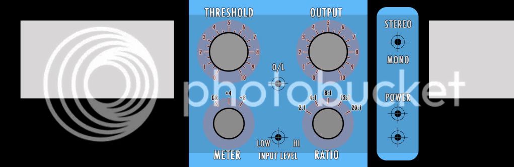
since this tread is lurking towards graphic design thanks to MrZpliff's art, here is a sketch of my frontplate for the double LA4 I'm working on these days....
All comments welcome !!!
The method should be the same as what I did with my Altec preamps (http://www.groupdiy.com/index.php?topic=28723.20), simple, cost effective, fully customizable !!!
The Vu meters will be AL22 from Sifam (I still have to figure out the Led upgrade on these as there were 12V lamps before), I should be using some Mentor knobs... Cheers, Piotr.
since this tread is lurking towards graphic design thanks to MrZpliff's art
, here is a sketch of my frontplate for the double LA4 I'm working on these days.... All comments welcome !!!
The method should be the same as what I did with my Altec preamps (http://www.groupdiy.com/index.php?topic=28723.20), simple, cost effective, fully customizable !!!
The Vu meters will be AL22 from Sifam (I still have to figure out the Led upgrade on these as there were 12V lamps before), I should be using some Mentor knobs... Cheers, Piotr.
Looks nice Piotr.
dunno,but it seems like you need two more holes for the overload-leds. I forgot them also.
Edit: Forget it ! I see you got it
Quoting myself from yesterday concerning stereo-calibration:
dunno,
Edit:
Forget it ! I see you got it Quoting myself from yesterday concerning stereo-calibration:
MrZpliff said:Hi again guys !
... so, I finally found some time and calibrated both my units.
Went rather smooth. Followed the instructions in the manual, 11 - calibration and 12 - Ratios.
What I can't really grasp is 15 - Stereo Threshold trim. should i put the voltage on the stereo link (point 15) on
each unit and do it like the manual or should I just switch to stereo mode and feed an equal signal to both channels
and check that the compression is equal ? (within reasonable limits)
Should I even bother ?
How did you do it guys ?
snipsnip
Well-known member
Hi Guys,
Im thinking of doing a pair of these.
What are people finding it costs per channel?
Thanks a lot
Jake
Im thinking of doing a pair of these.
What are people finding it costs per channel?
Thanks a lot
Jake
Nick Franklin
Well-known member
- Joined
- Feb 16, 2009
- Messages
- 118
Mine's nearly done... it's been about $200 australian per channel
Piotr
Well-known member
The total cost per channel is roughly 150 euros, a little more or less depending on the case, vu meter, transformer...
dustbro
Well-known member
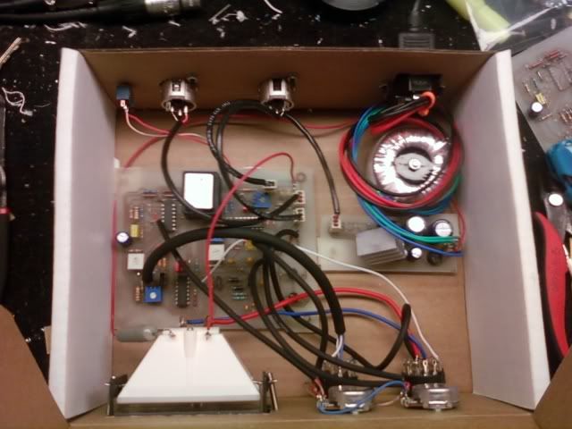
Found the perfect place to mount the ope A262A2E. Just drilled some holes and bent the legs underneath to hold it in place.
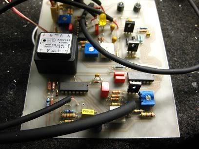
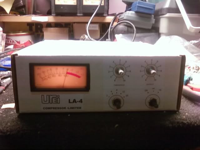
I havent gotten a real box for it yet, so I threw it in a cardboard box for beta testing. So far, it sounds 95% like my original units. I'd have to say that this version with the nsl32 and oep has the same compression character with a bit more open top end.
I ended up using an Antek AN-0118 wich is 18V - 10VA (.27A) and can power a single unit with no issues. Been powered up and in use for about a week now.
Sorry about the pic sizes... photobucket is acting strange
Luny Tune
Well-known member
Really cool to hear some feedback on the sound compared to the original, thanks! I'm soon getting two old Blackfaces on the tanle for recapping and check-up. I'll have a chance to test it thoroughly myself then.
And your box there looks waaaay cool! ;D ;D ;D
Gives me an idea for a design with a white front plate and wooden side panels like the original dbx163 comps I have. Look at your picture and see the brown side of the folded card board on the sides. Looks like wood panels on the picture... That would look sooo cool for stand alone units.
Similar threads
- Replies
- 0
- Views
- 3K
- Replies
- 38
- Views
- 10K
Latest posts
-

-

-
 Sound Skulptor: Pre's, Compressors, Tape Simulator, Professionnal Audio Kits
- Latest: Quantum J Audio
-

-

-
YAMAHA Ne80200 Opamp crackling noise repair, Schematicand pcb available
- Latest: cajitastompboxes
-