geoff004
Well-known member
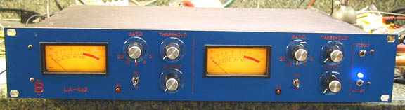
Gachet said:I'm still having an issue when connecting the units in stereo mode.compession becomes huge and strange!!!
Make sure that you add a ground where it's missing (is it IC2?) - it's not in front of me, but I remember my unit doing the same thing until I added the ground. Also the meters would act really strange.
")