LA-4 Help Thread!

GroupDIY Audio Forum

Help Support GroupDIY Audio Forum:

This site may earn a commission from merchant affiliate links, including eBay, Amazon, and others.
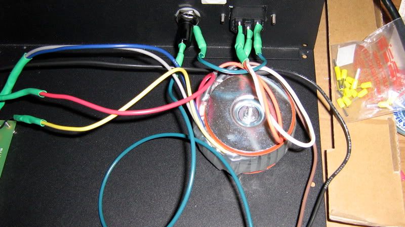
Quick question about wiring the audio transformer. I have the OEP a262a2C, which as far as I can tell from looking at the datasheet is the same as the a262a2E aside from the mu metal covering. Looking at Luny's wiring scheme, there are some pin connections that are shorted. To short them, I would connect them to nothing. Right?

For example, wiring the primary. Transformer + to A4, transformer - to A1, and then just jumper A2 and A3 together and Bobs your uncle.

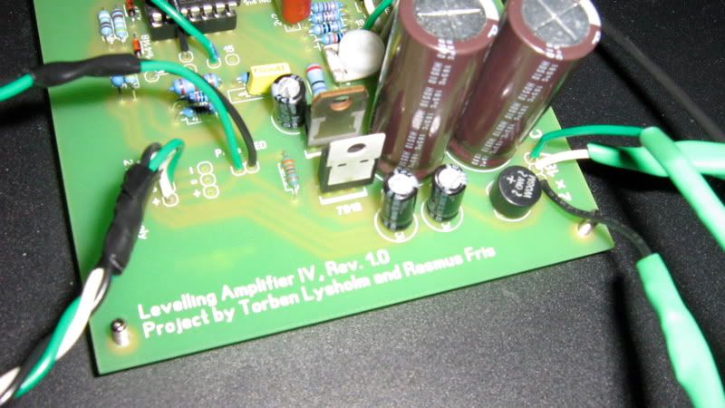
Another quick question. I am doing a dual mono version, and I have no plans on ever doing stereo linking. Can I just leave all the parts out for stereo linking? If it will work out better, I'll wire in a switch for that, but would like to save myself the extra work of drilling and mounting parts I don't plan on using.

Assembly starts tomorrow. I still have to pick up a couple of small parts, but I hope to have a lot of the mounting and metal working finished by the end of the day, and if I really work at it, get it all wired up by Thursday. I'll try to remember to snap some pics as I go along. Piotr, I hope you don't mind, but I kinda sorta modelled my front panel layout from yours.  ;D
 
Backwards...

Stereo linking... "All the parts"? If you mean the switch and the two wires connecting it to the boards, then yes. Just donøt mount it.

When shorting the windings it doesn't necessarily mean that they're then not connected to anything else. In audio, when using two windings in parallel you connect the ends of the windings to eachother and thatøs where you feed your signal in to or tap it from as well. In series you connect one winding's - end to the next winding's + end and then connect the circuit to the two loose ends.

Observe that my suggestion is to connect the transformer backwards "To transformer" on the board goes to the transformers original secondary winding and it's primary winding goes to "From transformer" on the board.
 
Hey guys. Got it workin!!! amazing what the correct resistors will do. The meter calibrated perfectly. Now with the issue of distortion, I love some good distorted compression but mine is distorted after about 3db of compression at 4:1, I've been tweaking the ratio and threshold pot to where it's the cleanest, is there anything else I can do?

Thanks for everyones help on this.
 
Congratulations on getting your unit working Ben! Going to post a picture soon?

Well, I had a pretty good couple of days. I have spent it working hard on my front plate. My very first attempt at it. It took a long time to do, and I only have one channel in right now, but I am pretty stoked about it! I still need to engrave it, but I am just so excited about it I had to share!

Its not perfect. I don't have fancy tools to work with, so I used my hand drill for all the holes, a jigsaw and hand file for the cut outs, and then my dremel to de burr and clean up everything. Its not perfect, but with the parts in, it looks pretty damn close (just don't look at the unfinished side). Here is the pic:
 
I don't mean to be a pain, but is there any real advantage to using shielded wire over twisting wires? I am prepping all my wire right now which is shielded, but it is a pain to work with, and it's going to add a lot of bulk into the enclosure that I don't really want to have. Shielded wire is also very pricey. In Luny's pdf he says that twisting wires will work fine, but I just want to make sure I can go unshielded and not miss out on something. Maybe I could just use the shielded for the input and outputs?

Thanks.
 
Flipped the power switch, I got me power. Groovy! I haven't connected the PSU into the circuit yet, because I need to make sure of one tiny little thing. My regulators are outputting a rock solid 25V, not the 18V I was expecting to see. There is a drop in voltage between the input and the output of the regs, but only a couple of volts.

While I was writing this the fuse popped. I am hoping that its because I left it on with the PSU wires unconnected for too long, but if thats not the case, please let me know. I have a 250mA fuse as stated in the schematic.
 
something doesn't seem right.  As I'm sure you know, a fuse pops when you draw too much power for it too handle, the power supply really shouldn't be drawing much current at all, and 18v regulators should not put out 25v.  Their whole job in life is to regulate a slightly higher voltage to a steady 18v. 

What's the make and model # for your PT? 

in the mean time check this out, I reference it all the time...

http://www.diyfactory.com/data/transformer_connections.gif
 
Hey guys, just wondering if anyone has any ideas how to clean up the sound of this a little bit, I dig the vibe but I'd like it if the vibe didn't kick in after just 3dB or so of compression. Will changing all the resistors to 1/2W or changing out the optos be what it needs?
 
MY PT is a Hammond 182k9 which is supposed to give me 18V CT on the secondary. My next plan of action is to test the actual output of the transformer. I couldn't get in there yesterday. On the regs I was measuring 27V or so going in, 25V coming out. Checking over the diagram, I do have the PT hooked up correctly. How easy is it to damage the PT? When I first tested it, I had the primaries wired wrong, which resulted in no power at all.

The fuse- I knew it! Damn! Expletive! I'll check it over for shorts again, but i may have a clue. When I hook my voltmeter up to the positive lead and neutral on the PSU, it does not give me a reading. Same when I hook up the negative and neutral. Could that be a clue to the problem? I have an LED hooked to the power LED points on the board, but I do have a resistor in place to limit the current that it draws. The power was on for at least 5 minutes before the fuse popped.

I'l check it all over again. Thanks for the help!
 
Transformers are pretty robust, I don't think you damaged it.  Voltage regs, not so much, I've burnt out many of them. 

Looking over the data sheet, seems like you should have the red secondary going to one 18v pad, the blue and the gray to 0 and the yellow to the other 18v.  So you should be able to measure ~18v from red to blue/gray and ~18v from yellow to blue/gray.  I usually like to wire my transformers to a terminal strip and test the voltages before I hook it up to the power supply as it's something I've screwed up many times. 

Can you post a close up pic of just the power supply section? 
 
OK. I got some pics. I had to use some different wire to hook the trafo into the board because the wires were just too big to fit in the holes. Red from the trafo is hooked to green, yellow is hooked to black, and grey/blue is hooked to white. The other picture shows my PT wired up. Its messy I know.

I disconnected the power transformer from the board in order to measure the individual secondaries. Both showed between 9V and 10V with 120V coming in on the primary. I think I may have an idea. Hammonds data sheet may be a little misleading. This trafo says 18V CT when hooked in series, but each individual secondary is rated at 9V, not 18V. So I have a 2 x 9V. Crap (dunce cap is on).I am even more confused now. How am I getting 25V? Maybe a short or a bridge?

I have a 2 x 18V trafo lying around that I can throw in there. I'll replace the regulators and give that a try.
PTcloseup.jpg


Powersupplycloseup.jpg


Well, looking at your power supply I can't see anything wrong.  When you say...

On the regs I was measuring 27V or so going in, 25V coming out.

I'm not sure what you mean, that just seems bananas with with the 2x9v transformer.  Let's make sure we're on the same page, with the correct transformer you should be measuring 18vac coming into the psu on each of the secondaries (measured from the secondary to the ct) and then coming out, +18vdc from the + pad to the 0 pad and -18vdc from - pad to 0 pad (where you have the black, green, and white wires)


Bananas indeed. We are on the same page as far as the measurements go. When I took the first voltage measurements on the PSU output, I put my black probe on the 0V, and the red on the + wire, but couldn't get a reading at all. Then I tested from the ouput leg of the regulators to the end of the wires, and got my +25V. Then I measured the V going into the regulator input, and it was around 27V or so. This could just be me not taking proper measurements (probably), but when I hooked my meter up properly to the PSU output (neutral/+, neutral/-), no matter how I set the DC range, it would not read. Maybe I damaged a solder pad in there. I had a solder bridge to fix at one point, and I could have lifted the pad on the 0V output.

I need to check, but I am pretty sure I was getting positive voltage of the negative regulator. I'll double check that though. It was late, and I was one confused/frustrated dude.

Thanks for all your help so far Substitute. I'll reconnect and double check all my measurements before going further. I was going to redo the whole thing, but then I won't know what I did wrong.
 
I'm not quite ready to fire these up yet, still need to order meters, but I wanted to go over which trimmers do what since they're not labeled on the boards.  Comparing the board to the schematic it's not too hard figure out, but I thought it would be handy to have a list to look at during calibration.  Please correct me if I'm wrong.

la4-trimmers.jpg


1) common mode adjust R4
2) zero adjust R51
3) meter tracking R49
4) threshold trim R57
5) ratio R34
 
Insomnia, I'll hook mine up tomorrow afternoon and take some measurements on the regulators and what not for comparison.  What are you using for a meter?  I mean what dmm are you using?

 
I am using a Victor VC9801A that I bought from Lees Electronics in Vancouver.

Heres the link:

http://www.leeselectronic.com/catalog/product_info.php?cPath=15_16&products_id=7848
 
I just got home from work and decided to tackle this thing. I inspected the PSU output wires, and I found that the solder pad for the 0V had indeed lifted off of the board. After repairing this with some solid core copper wire, I tested again. I am now getting -12 and +12 which is much more sane. I think this may have also been the cause of my blown fuses.

Just have to put the right transformer in and test it again. Should I replace the regulators anyways?

Thanks for all the help!

By the way substitute, I checked out your MILA. Looks pretty sweet! I haven't had a chance to check out your sound file yet, but I'll try in the next couple of days.
 
Back
Top